,167$//$7,21
&RS\ULJKW7UDFH(QJLQHHULQJ&R,QF 7HOHSKRQH 3DUW1XPEHU
WK
6WUHHW1( )D[ 2FWREHU
$UOLQJWRQ:$86$ ZZZWUDFHHQJLQHHULQJFRP
3DJH
AC and DC Wiring Separation
Do not mix AC and DC wiring in the same conduit or panel. A separate conduit should be used for
each. Induced current in the DC conductors could cause confusion with the inverter’s
microprocessor. Where DC wiring must cross AC or vice-versa, make the wires at the crossing point
90
°
to one another. Consult code for details of DC and AC wiring in vicinity to one another.
AC Wire Connections
The AC terminals are located on the front panel of the inverter chassis. A six-station terminal block is
provided to make the AC connections. The terminal block is used to hardwire the AC input and AC
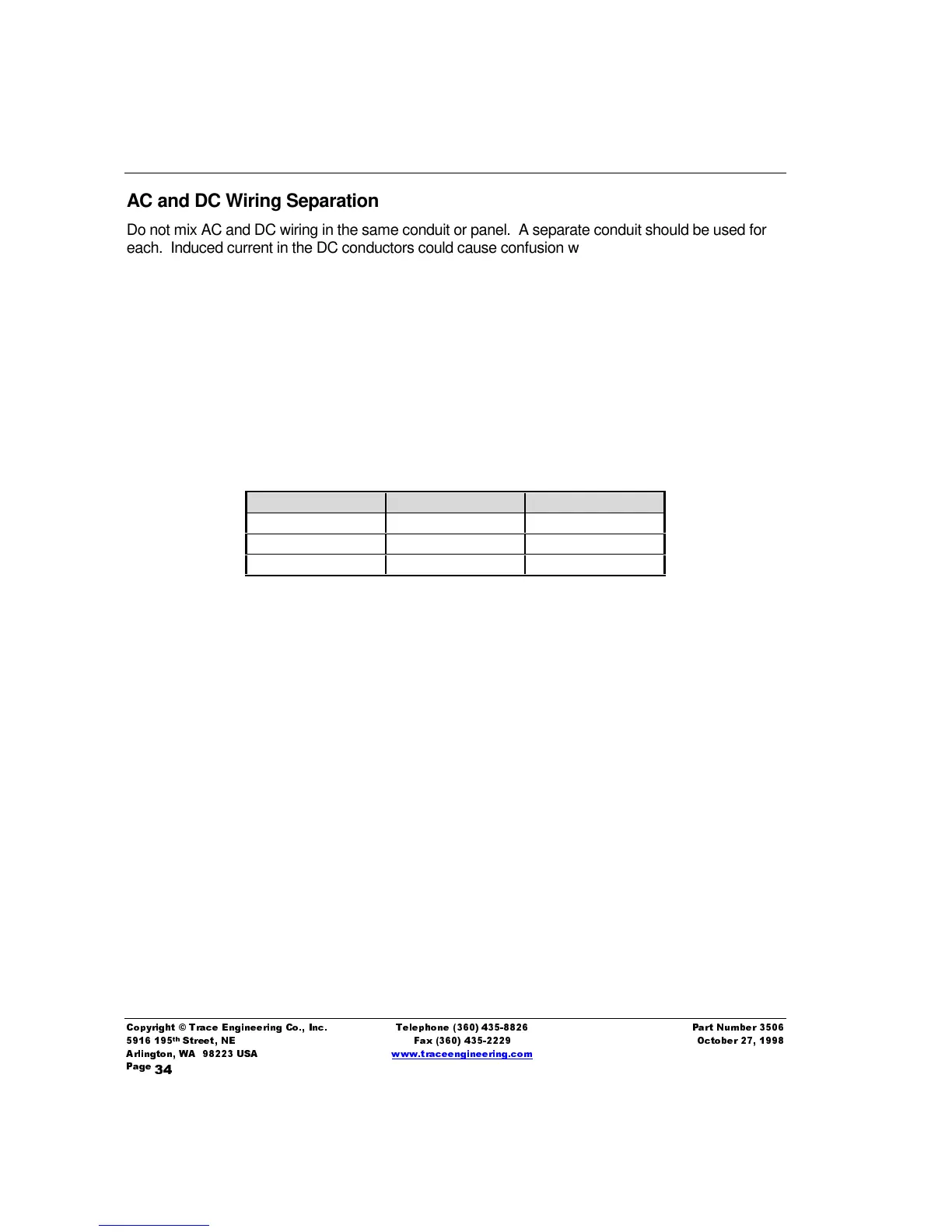
output. All terminals are labeled on the inverter. Table 9
"Recommended Minimum AC Wire Sizes"
on Page 34 gives suggestions for wire sizing.
Table 9
,
Recommended Minimum AC Wire Sizes
Inverter Model 120 VAC Input 120 VAC Output
M2012 10 AWG 12 AWG
M2512 8 AWG 10 AWG
M3012 8 AWG 10 AWG
AC Disconnect Device
Standards and regulations require an external disconnect switch in the AC input wiring circuit. AC
breakers will meet this requirement. If the vessel is equipped with a generator, an AC source
selector switch (such as Blue Sea Systems' part number 8032) is required. This particular switch
also includes circuit breakers that protect both the ungrounded current-carrying conductor (Hot 1)
and the grounded current-carrying conductor (Neutral). Also included are polarity indicators and a
Power On indicator, all of which are required by ABYC standards (polarity indicator is not required if
an isolation or polarity transformer is installed. The AC disconnect device must be located within 10
feet of the shorepower entry, measured along the cable. The power On indicator should be located at
the AC load center.
Ground Fault Interrupting Outlets (GFCI’s)
Trace Engineering has tested the following GFCI’s and found them to work satisfactorily with our
inverters:
LEVITON 6599
PASS & SEYMOR 1591RI 4A957
ACE Hardware ACE 33238