237,216
&RS\ULJKW7UDFH(QJLQHHULQJ&R,QF 7HOHSKRQH 3DUW1XPEHU
WK
6WUHHW1( )D[ 2FWREHU
$UOLQJWRQ:$86$ ZZZWUDFHHQJLQHHULQJFRP 3DJH
The RC7 displays its information on a LCD screen and has multiple modes. A menu tree
accompanies the RC7 to help navigate the RC7’s many features. The RC7 is the only way to
change the setpoints of the inverter. Once the desired changes have been made, the RC7 may be
unplugged and these changes will be retained, even if the inverter is completely powered down.
When the RC7 is connected to the inverter, the inverter’s status LED still operates normally.
Installation and operating instructions are included with the RC7.
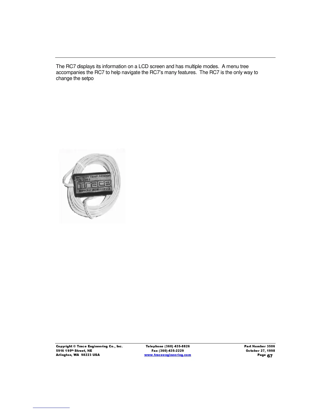
%DWW HU\7HPSHUDWXUH6HQVRU %76
An optional plug-in external battery-temperature sensor (BTS)
automatically fine-tunes the charging
process of the charger. When the temperature sensor is installed, the inverter/charger adjusts the
BULK
and
FLOAT
charge voltage
.
A BTS is shown below.
If the temperature sensor is NOT installed, charger configuration
must be manually set.
Install the BTS on the side of the battery below the electrolyte level.
It is best if the sensor is placed between batteries and if the
batteries are placed in an insulated box to reduce the influence of
the ambient temperature outside the battery enclosure. Ventilate
the battery box at the highest point to prevent hydrogen
accumulation.
The BTS provided may be extended beyond the standard 15 feet
by an additional 20 feet using standard phone cables with RJ-11
plugs. However, locating your batteries 35 feet from the inverter
exceeds the recommended distance and requires heavier battery
cables.
%DWW HU\&DEOHV
Trace Engineering UL listed battery cables are available from Trace Engineering authorized dealers
in various lengths to ensure maximum power transfer between the inverter and batteries. They are
available in two sizes: 2/0 and 4/0. Cable lengths include 1½, 3, 5, and 10 feet for both sizes. A 4/0
cable length of 15 feet is also available. All Trace Engineering cables have red or black color-coding,
and sealed, crimped ring terminal ends.