$33(1',;&5()(5(1&(7$%/(6*5$3+6
7UDFH(QJLQHHULQJ&R,QF 7HO 3DUW1XPEHU
WK
6WUHHW1( )D[ 2FWREHU
$UOLQJWRQ:$86$ ZZZWUDFHHQJLQHHULQJFRP
3DJH
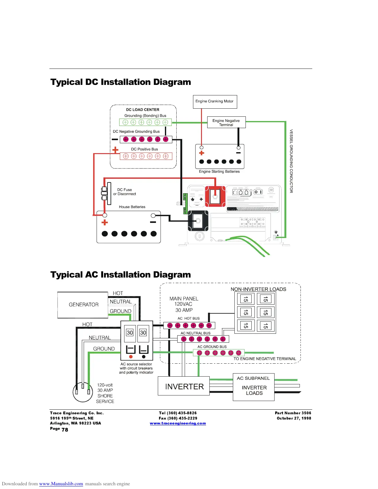
7\SLFDO '&,QVWDOODWLRQ'LDJUDP
7\SLFDO $&,QVWDOODWLRQ'LDJUDP