48,&.,167$//
&RS\ULJKW7UDFH(QJLQHHULQJ&R,QF 7HOHSKRQH 3DUW1XPEHU
WK
6WUHHW1( )D[ 2FWREHU
$UOLQJWRQ:$86$ ZZZWUDFHHQJLQHHULQJFRP 3DJH
4XLFN,QVWDOO
Marine electricians with experience installing inverters may follow the installation instructions in this
section. This section assumes knowledge of current ABYC standards, applicable Federal
regulations, and safe working practices. For all others, the following
Installation
chapter describes
ABYC standards, Federal regulations, and safe working practices.
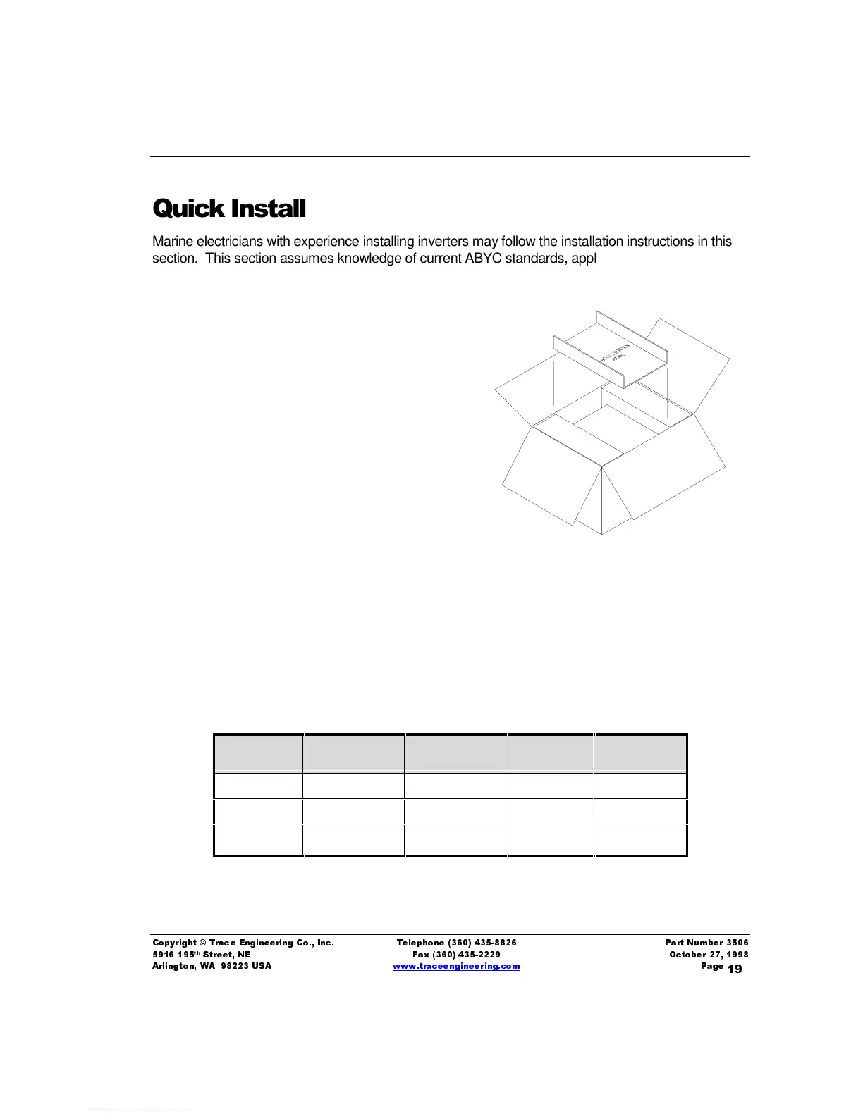
Unpacking – Before beginning, unpack the inverter/charger, record
the serial number on the inside cover of this book and on the
warranty card. Retain packing materials for future use. Ensure
that all components listed on the Packaging Materials
sheet are included. If any components are missing,
please call Customer Service at (360) 435-8826.
Mounting and Location – Mount the unit securely in a
horizontal position in a clean, dry, ventilated enclosure.
Do not mount the unit in the same enclosure as vented
or maintenance-free vented batteries. Do not mount the
unit in the engine room of gasoline-fueled vessels. Install
appropriate strain-reliefs and conduit. Bolt the unit securely to
deck, shelf, or bulkhead. Allow adequate clearance to allow access
to the front panel. On U.S vessels, installations must conform to the requirements of 33 CFR
183.410.
'&&DEOLQJ
Determine the correct DC cable to use (also see
Table 5, Maximum Fuse Rating in Free Air
on Page
28) for the inverter model and length of run for your specific application from the table below:
Table 2, DC Cable Sizing in Free Air
Inverter
Model #
Typical DC
Amps
1 to 3 feet
One Way
3 to 5 ft
One Way
5 to 10 ft
One Way
M2012 200 Amps 00 0000 0000
M2512 250 Amps 0000 0000 0000
M3012 300 Amps 0000 0000 0000
• Ensure that the On/Off switch on the front panel of the inverter is in the Off position before you
begin the installation.