,167$//$7,21
&RS\ULJKW7UDFH(QJLQHHULQJ&R,QF 7HOHSKRQH 3DUW1XPEHU
WK
6WUHHW1( )D[ 2FWREHU
$UOLQJWRQ:$86$ ZZZWUDFHHQJLQHHULQJFRP
3DJH
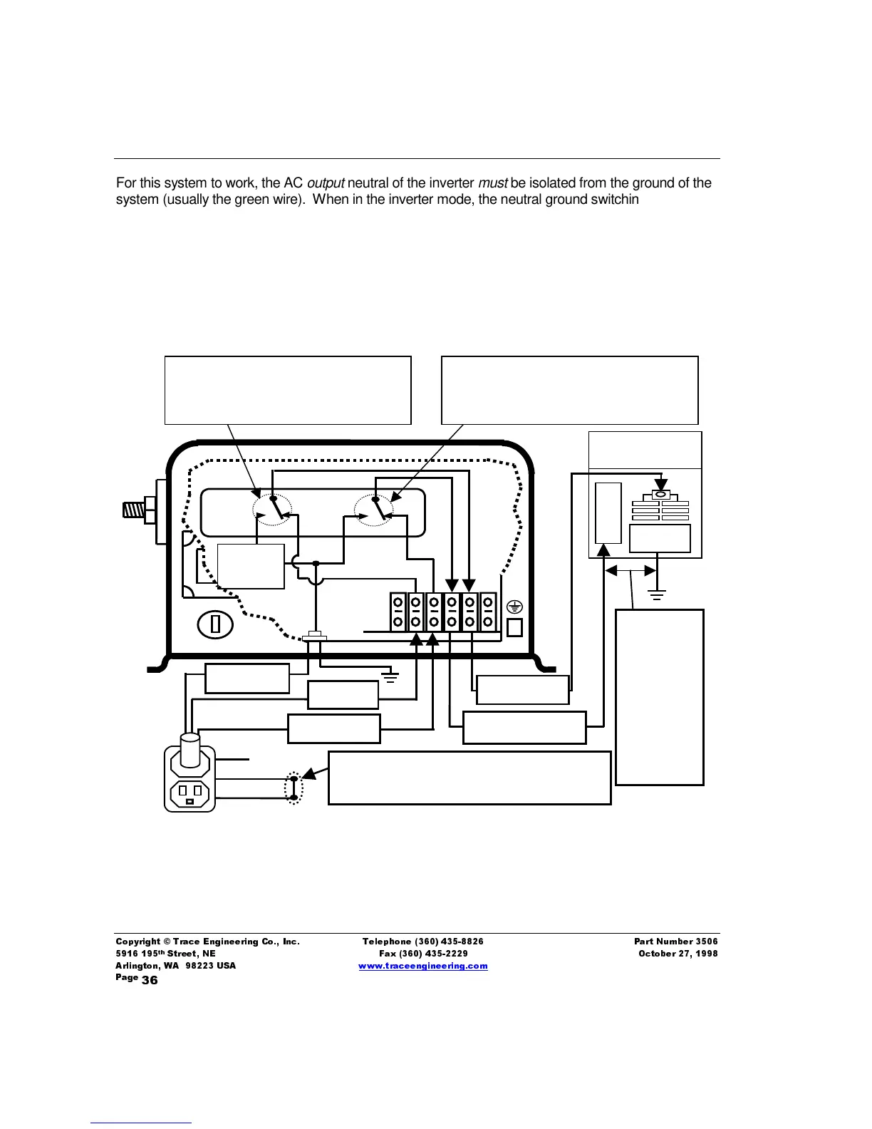
For this system to work, the AC
output
neutral of the inverter
must
be isolated from the ground of the
system (usually the green wire). When in the inverter mode, the neutral ground switching relay will
automatically connect (bond) the output neutral to ground, and when in charger/pass-through mode,
the ground and neutrals will be bonded to one another at the AC source (generator or shore power).
The diagram below graphically describes the ground switching system in the inverter for a unit
connected to an external AC source (generator, grid etc.) and passing the AC power through the
inverter to the AC sub-panel.
GROUND
NEUTRAL
HOT
RY-A
RY-B
HOT OUT
The
neutral
conductor
shall be
insulated
from the
equipment
grounding
conductors
or
enclosures
NEUTRAL OUT
HOT IN
NEUTRAL IN
GROUND
Neutral-to-Ground “BOND” is provided by the
external AC source for entire AC system
AC Sub-panel
Inverter loads
N
E
U
Inverter
AC
out
GND
Relay RY-A connects the AC input and
AC output HOT sides together to allow
power to pass through the inverter when
AC is present at the inverter inputs.
Relay RY-B connects the NEUTRAL (IN)
from the external AC source and NEUTRAL
(OUT) of the loads together when AC is
applied to the inverter.
Figure 10, Neutral-to-Ground Switching with External AC