19 MN1007-C
To use any of the background adjusted modes of operation (including Bq/cm
2)
, the user must take a background
reading for the chosen probe.
[See section 4.7 for further information on background measurement]
Probe Connection
Each probe is supplied with a flying lead terminated with an industrial specification IP68 (mated condition) coupling
connector [See Section 4.2.1 – Connecting the probe]
Note that the plug and socket are polarised. Please observe the red dot registration markings when connecting
the probes.
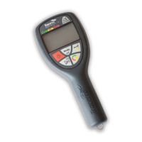
Indicator LEDs
Three LEDs indicate the current processing stage when using the integration measurement mode. The integration
measurement sequence is shown below.
1. Green rate LED – indicates that the measurement is in real-time. The display reading will fluctuate according to
the random nature of the radiation source.
2. Amber integrate LED – indicates that the instrument is busy. The LED will continue to flash over the duration
of the integration period.
During this period the display continues to show an averaged measurement with a one second refresh rate.
3. Red stop LED – indicates that the measurement is complete. The display no longer updates while the red LED
is flashing.
Press the Rate/Int./Stop
key again and the instrument returns to rate mode (1). The sequence is now complete.
[See also Section 4.5 Integration Function]
 Loading...