21 MN1007-C
4.2.3 Switching on the instrument
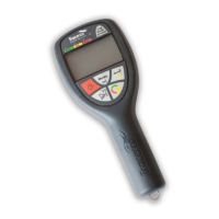
Pressing the power
key will turn on the monitor. A self-test routine enables all LCD segments and the three
indicator LEDs are illuminated in sequence.
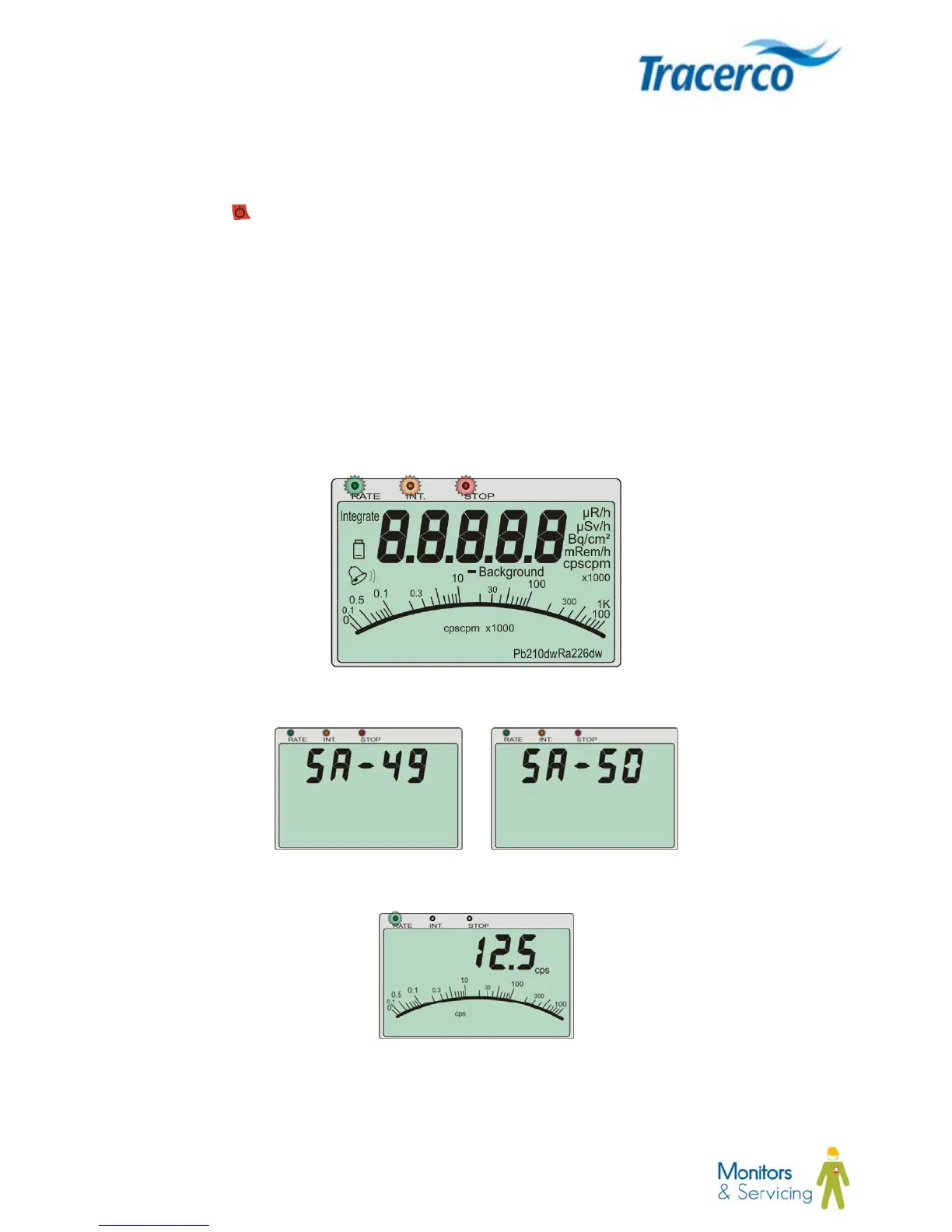
Following the initialisation, visual acknowledgement of the selected probe type is displayed briefly as illustrated
below. SA-49 indicates the GM probe is connected; SA-50 indicates the Scintillator Probe is connected.
The start-up sequence is complete once the green LED starts flashing. The monitor is now ready for use.
At this stage the unit measurement presented to the user is dependent upon the operating mode and alarm
settings used when the instrument was last switched off. In the illustration below the instrument was last used in
cps mode and no alarm was set.
4.2.4 Start-up sequence illustration
Figure 4 - Start-up sequence
 Loading...