- 4 -
3.2 Controls
A. Hydraulic Flow control valve
B. Hydraulic regulation valve
J. Trigger Switch
C1 C2
C. Fork handle
S. Spring knob
C1. Manual position
C2. Auto position
D. Manual/Auto selector
E. Start/Reset push button
F. Speed selector
G. Main connect switch
H. Indicator light
K. Emergency push button
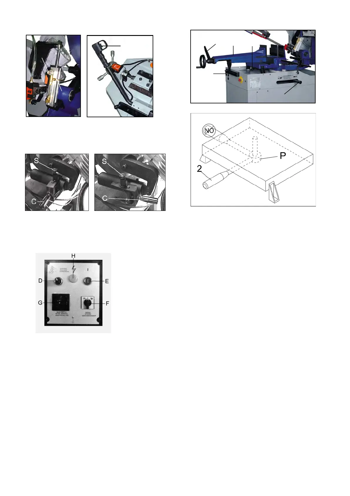
3.3 Vice adjustment
- The device does not require any particular
adjustment; in case of excess play of the sliding guide,
tighten slide screw more.
To move the vise in either direction, the vise jaw must
be unlocked at two points.
- Release the track support by turning handle (1)
counter-clockwise.
- Release the vise by moving the lever (2) to the left.
- The vise (5) may now be moved to right position (7)
or left position (6) by pushing it with one hand on the
vise and the other hand on the track handle (1).
- Once in position, move the lever (2) to the right to
lock it into position. If the lever (2) is not between
the vise/bed mounts and facing the user, then the
vise will not be able to lock. If the vise lever (2) has
gone beyond or is obstructed by a vise/bed mount,
then use the following procedures.
- Adjust the lever (2) by grasping at the pivot point (P)
and lowering it, which may assist in the adjustment.
The lever can now be freely rotated into a more
convenient position. Some movement of the vise
jaw may be required. Raise the lever (2) then move
to the right to lock.
- Lock the track support (1) by turning handle
clockwise.
Clamping the Work Piece
- Place work piece between the jaws.
- Use the hand wheel to approach the vise jaws to the
work piece, leaving 3-4mm of space. Lock down work
piece and raise the lever (4). Push start button (E).
When the cutting cycle is finished, release vise by
lowering lever (4). Upon releasing the lever (4), the
vise jaw will open to the same distance that was set
initially. This allows for rapid loading of same size
material.
A
B
J
4
5
2
1
3