- 7 -
- Do not use blades of a different size from those
stated in the machine specifications.
- If the blade gets stuck in the cut, release the running
button immediately, switch off the machine, open the
vice slowly, remove the part and check that the blade
or its teeth are not broken. If they are broken, change
the tool.
- Before carrying out any repairs on the machine,
consult the dealer.
5 ADJUSTING YOUR MACHINE
5.1 Blade tension assembly
The ideal tension of the blade is achieved rotating the
handwheel until it the microswitch, that actuates the
operation of the machine is actuated
WARNING: the position of this switch is factory set
during inspection, after having tightened the blade on
the lengthening values indicated by its manufacturer as
per specific dimensions set with the help of a special
instrument. When replacing the blade, if the
thickness and the width differ, it will be necessary to
correct the projection of the switch. For this purpose
we suggest to strictly select blades having the same
features as mounted originally.
5.2 Adjusting the blade guide
- Disconnect the machine from the power source.
- Use a Hex. Wrench to loosen Hex. Socket screw (A)
on the square lock plate.
- Hold the handle (B) and slide blade guide block as
close as possible to the material without interfering
with the cut
- Tighten the Hex. Socket screw (A).
- Reconnect the machine to power source.
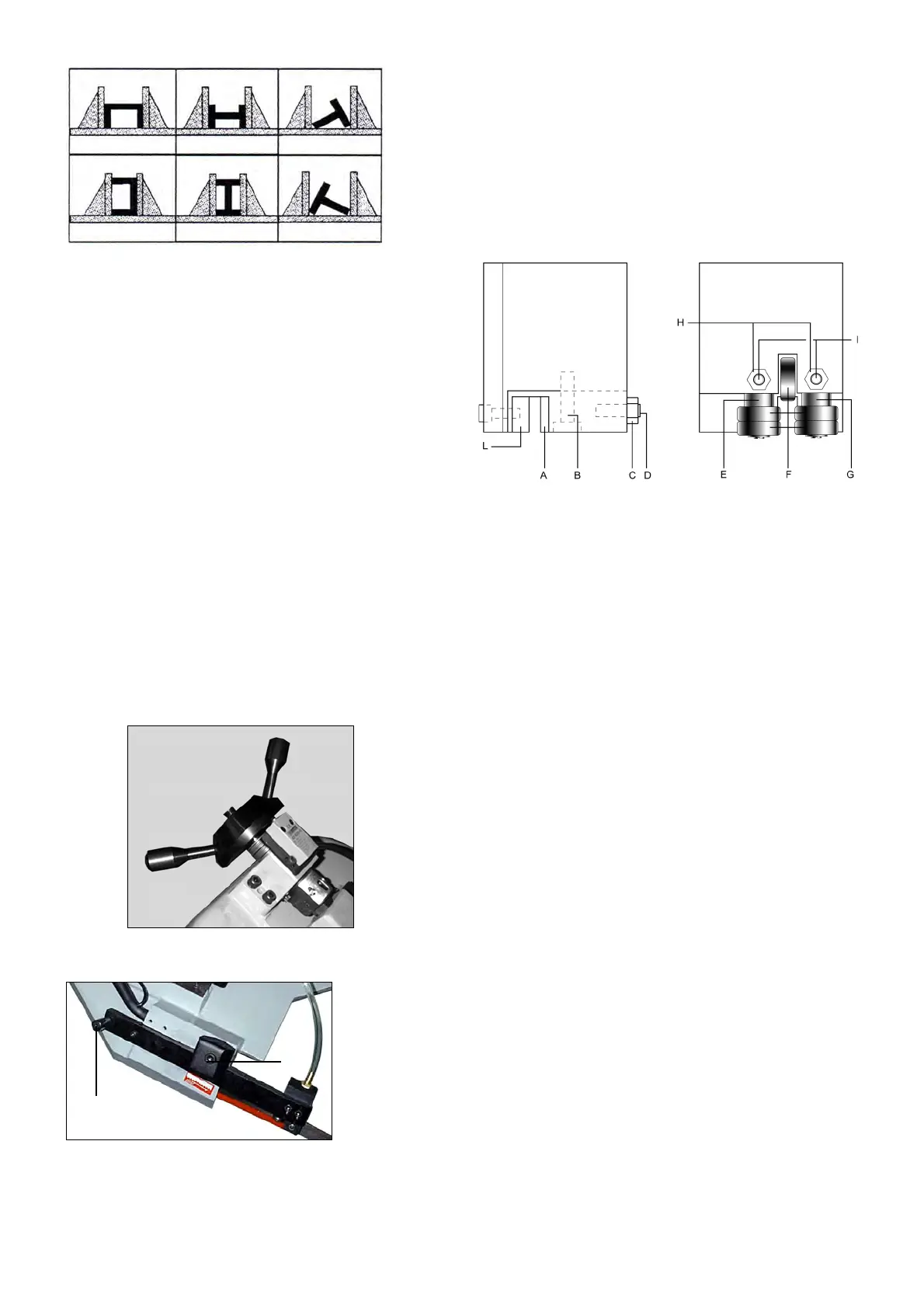
Blade guide blocks
The blade is guided by means of adjustable pads set in
place during inspection as per the thickness of the
blade with minimum play as shown in the figure.
In case the blade needs to be replaced, make sure to
always install 0.9mm thick blades for which the blade
guide pads have been adjusted. In the case of toothed
blades with different thicknesses adjustment should be
carried out as follows:
- Loosen nut (C), screw (B) and loosen dowel (D)
widening the passage between the pads.
- Loosen the nuts (H) and the dowels (I) and rotate the
pins (E - G) to widen the passage between the
bearings (F).
- To mount the new blade: place the pad (A) on the
blade, loosening the dowel, allow a play of 0.04 mm
for the sliding of the toothed blade, lock the relative
nut and screw (B), Rotate the pins (E - G) until the
bearings rest against the blade as indicated in the
figure and then secure the dowels (I) and nut (H).
- Make sure that between the blade and the upper
teeth of the pad (L) this is at least 0.2 - 0.3 mm of
play; if necessary, loosen the screws that fasten the
blocks and adjust accordingly.
BEFORE PERFORMING THE FOLLOWING
OPERATIONS, THE ELECTRIC POWER SUPPLY
AND THE POWER CABLE MUST BE COMPLETELY
DISCONNECTED.
5.3Changing the blade
To change the blade:
- Lift the saw arm.
- Loosen the blade with the handwheel, remove the
mobile blade-guard cover, open the flywheel guards
and remove the old blade from the flywheels and the
blade guide blocks.
- Assemble the new blade by placing it first between
the pads and then on the race of the flywheels,
paying particular attention to the cutting direction of
the teeth.
- Tension the blade and make sure it perfectly fits
inside the seat of the flywheels.
B
A