- 5 -
3.4 Cutting angle adjustment
Cutting at angles
- Using the right side, angles can be cut up to 60
degrees. This requires that vise jaw to be set on the
left side (6). Use the procedures for 3.2 Vise
Adjustment to place it in left side position.
- Using the left side, angles can be cut up to 45
degrees. This requires the vise jaw to be set on the
right side (7). Use the procedures for 3.2 Vise
Adjustment, to place it in right side position.
- Unlock lever (3) and use the handle under the control
box to rotate the saw frame arm until you reach
mechanical stop and check if the index corresponds
to 45 degrees; if not, operate on the set screws to
make measures meet.
3.5 The base
- A structure supporting the SAW ARM (revolving arm
for gradual cutting and respective blocking system),
the VICE, the BAR STOP, the ROLLER for the support
of the material. The base houses the cooling liquid
TANK and PUMP.
3.6 Saw frame return stroke-limiting device
The hydraulic cylinder is ideal for the cutting of thin or
STAINLESS STEEL section bars, that determines a
constant lowering and consequently a good efficiency
of the blade throughout the work phase. By adjusting
the flow control valve (A), this device can be
accommodated to the different situations and
applications. Defectiveness in the control of the
lowering may be caused by the drop in braking power
of the device due to the long-term blowby of the
braking fluid.
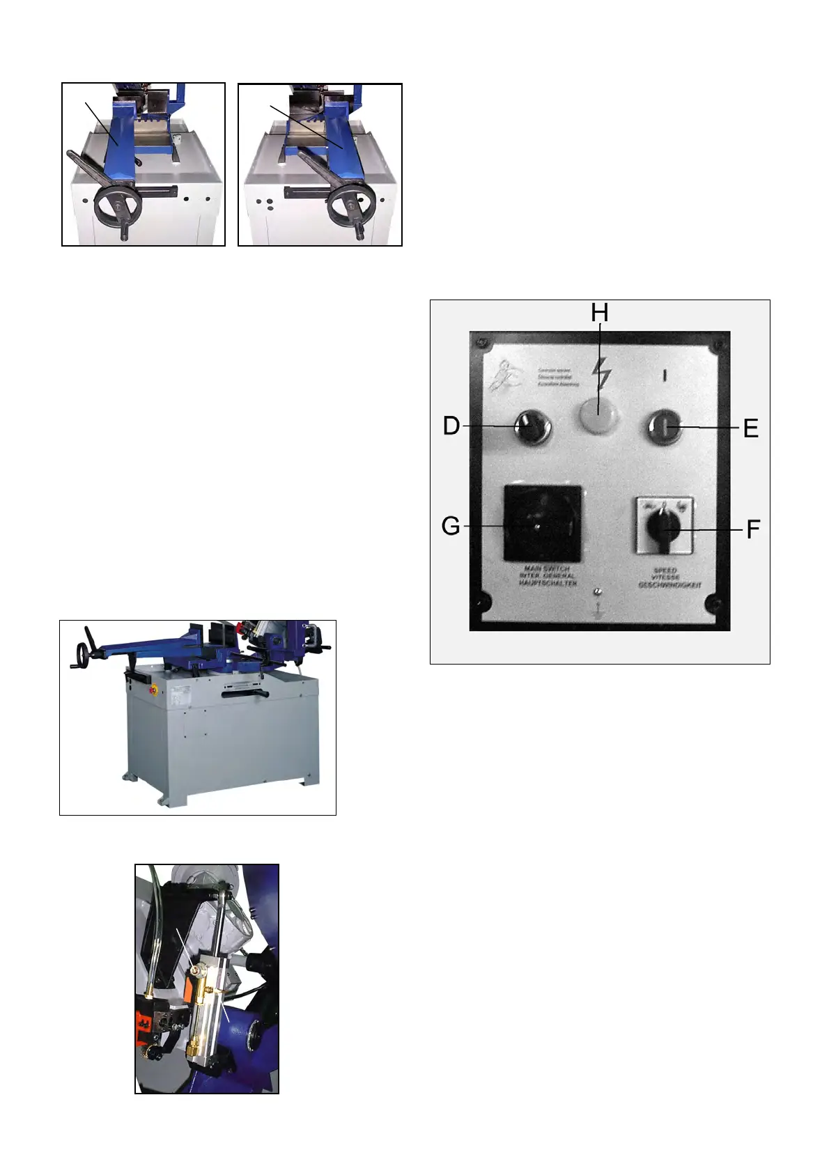
3.7 The operation cycle
Before operating, all the main organs of the machine
must be set in optimum conditions.
Operation Procedure:
A. Trigger switch operation
- Close the hydraulic flow control valve (A) by turning
the valve clockwise all the way to the end.
- Raise the saw arm.
- Lift the spring knob (S) to release the pin from its slot.
This will free the fork handle (C). Move the handle
to the manual position (C1). Lift the spring knob (S)
and secure its pin into its slot.
- Use manual/auto selector (D) to select handle icon.
- Select cutting speed by turning speed selector (F).
Turtle is low speed, rabbit is high speed, and ‘O’ is
neutral.
- Turn main connect switch (G) to the ON position.
Check that the indicator light (H) is on.
- Load work piece and clamp it properly.
- Fully open the hydraulic flow regulation valve (B) by
turning the valve counter-clockwise all the way to the
end.
6
7
A
B