Installation - Mechanical
CLCH-SVX009J-EN 29
3. Use field-provided spreader bars and slings to rig as
shown Figure 29. Straps can be used but careful
consideration must be taken not to damage equipment
panels.
4. Remove screws (Item 3) around parameter lip where
second level is attached to first level.
5. If unit is equipped with optional filter rack, insert
screws (Item 3) in vertical flanges on each side of filter
rack (see detail A in Figure 29). Screws installed to
support filter rack temporarily and must be removed
after reassembly.
6. Lift second level fan portion vertically to clear
parameter lip on first level portion of unit.
Repeat steps 1-6 in reverse order to reinstall second level
fan portion on the first level portion of unit. Lifting lugs
should be removed once reassembly is complete. Check
gasket between the two sections. In the event the gasket
between the two sections is damaged, replace with new
gasket (Item 4) (Part# GKT03823). See the figure below.
Note: If unit is equipped with a control interface, VFD or
electric heat, disconnect electrical wiring. Wiring
between fan motor and contactor or VFD can be
disconnected via quick connects in the control
interface or VFD box respectively. Electric heat
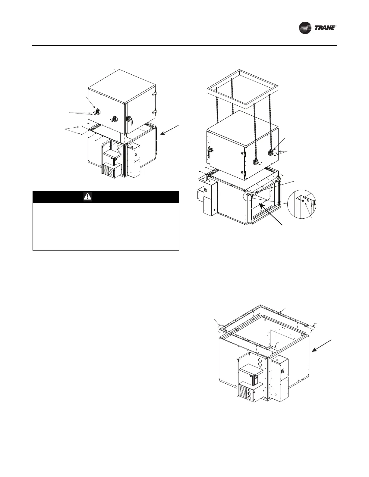
Figure 28. Remove screws, install lifting lugs
WARNING
Risk of Unit Dropping!
Improper use of the tie down brackets could result in
unit dropping and crushing technicians which could
result in death or serious injury, and equipment
damage. Do not use skid tie down brackets to lift the
unit. Tie down brackets are designed only to secure the
unit to the floor, housekeeping pad, or platform.
(3) Screw:
0.250 - 14 x 0.750
self-driller
(2) Screw:
0.313 - 18 x 0.875
sheet metal
(1) Lifting lug # LUG00180
Temporarily use for
lifting second level.
Airflow
Figure 29. Use spreader bars to lift top unit
Figure 30. Check gasket between sections, replace if
necessary
(3) Screw:
0.250-14x0.75
self driller
(3) Screw:
0.250-14x0.75
self-driller
Detail A
(2) Screw:
0.313-18x0.875
sheet metal
Airflow
(1) Lifting lug
#LUG00180
Temporarily use for
lifting second level.
4.254.25
2.25
First Level
Airflow
Joint gasket
should overlap
1/2 inch
(4) Gasket: 0.188T x 1.50W
# GKT03823
Align to the edge of the panel.