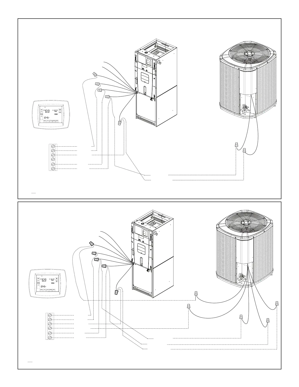
31
Air Handler Hook-up Diagram
1 Stage HP
Red
Yellow
Green
White
Blue
Orange
ellow
White
Blue
B
B - Blue
R - Red
W
G
Y
Y - Yellow
R
Red
O
Orange
Comfort Control
Air Handler
Field wiring
Yellow
Blue
Black
(X2)
Red
Orange
Heat Pump
Red
Blue
Yellow
Green
W2 Pink
W3 Brown
W1 White
Air Handler Hook-up Diagram
1 Stage Cooling
Red
Yellow
Green
White
Blue
ellow
White
Blue
B
B - Blue
Blue
W
G
Y
Y - Yellow
Yellow
R
Red
O
Orange
Comfort Control
Air Handler
Air Conditioner
Field wiring
Red
Blue
Yellow
Green
W2 Pink
W3 Brown
W1 White
• * For multiple stages of electric heat, jumper W1, W2, and W3 together if comfort control has
only one stage of heat
• * For multiple stages of electric heat, jumper W1, W2, and W3 together if comfort control has only one stage of heat.
STEP 6 - Using field supplied wire nuts, make
connections per hookup diagrams.