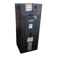
32
NOTE: Airflow Speed tap
adjustment is required
Air Handler Hook-up Diagram
2 Stage HP
Red
Yellow
Purple
Green
White
Blue
Orange
ellow
Green
White
Blue
B
W
G
Y1
R
Red
O
Orange
Comfort Control
Air Handler
Field wiring
Y2
Purple
Y2
Blue
X2
Black
Red
Y1
Yellow
Heat Pump
Orange
Red
Blue
Green
W2 Pink
W3 Brown
W1 White
Yellow
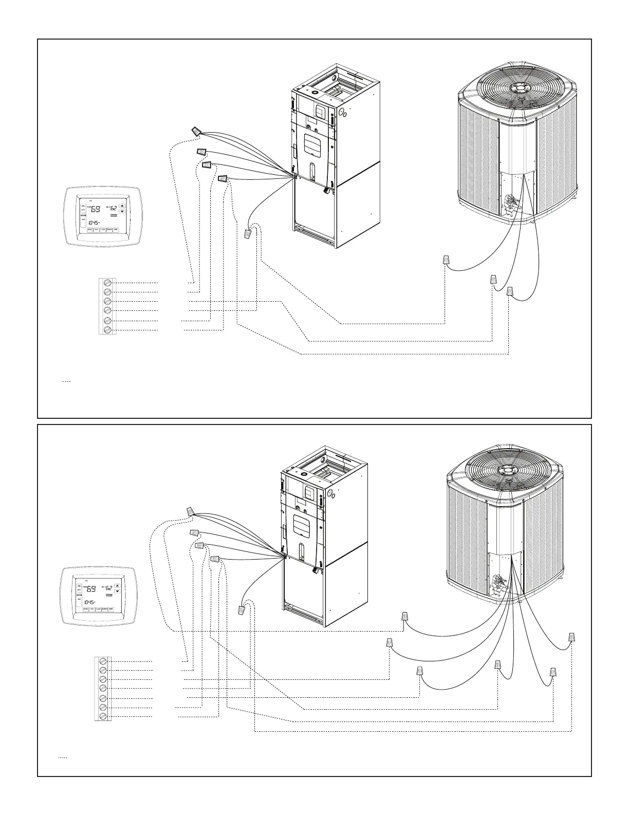
Air Handler Hook-up Diagram
2 Stage Cooling
Red
Yellow
Green
White
Blue
Purple
ellow
White
Blue
B
Blue
W
G
Y1
Y1
YL/BK
Y2
YL/RD
R
Red
Y2
Purple
Comfort Control
Air Handler
Air Conditioner
Field wiring
Red
Blue
Yellow
Green
W2 Pink
W3 Brown
W1 White
• * For multiple stages of electric heat, jumper W1, W2, and W3 together if comfort control has only one stage of heat.
• Airflow adjustment will be required for two stage applications.
• * For multiple stages of electric heat, jumper W1, W2, and W3 together if comfort control has only one stage of heat.
• Airflow adjustment will be required for two stage applications.
NOTE: Airflow Speed tap
adjustment is required