28
WSHP-SVX022A-EN
Installation
WARNING
Hazardous Voltage!
Failure to disconnect power before servicing could
result in death or serious injury.
Disconnect all electric power, including remote
disconnects before servicing. Follow proper lockout/
tagout procedures to ensure the power can not be
inadvertently energized. Verify that no power is
present with a voltmeter.
WARNING
Proper Field Wiring and Grounding
Required!
Failure to follow code could result in death or serious
injury.
All field wiring MUST be performed by qualified
personnel. Improperly installed and grounded field
wiring poses FIRE and ELECTROCUTION hazards. To
avoid these hazards, you MUST follow requirements
for field wiring installation and grounding as
described in NEC and your local/state/national
electrical codes.
1. Remove the unit and packaging from the crate. Inspect
the unit. Carefully remove the stretch wrap and
cardboard pieces. The installation literature and may be
found on the back of the unit in a clear, plastic bag. Unit
has been tied to skid by (2) shipping brackets.
2. Remove refrigeration panel and inspect the unit. Be
certain the refrigerant tubing has clearance from
adjacent parts. Verify that the electrical connections are
tight and in-place.
Chassis Refrigeration
Front Panel
Shipping Brackets
Mounting Locations
3. With the chassis still on the subbase, align the unit to
the wall. If unit contains an outside air option, align the
wall cutout to the subbase outside-air cut-out. Level the
unit per plan requirements. Mark the four mounting
locations for wall sleeve mounting to the wall. The
dimensions should fall in line with Step 5.
4. Install the wall flange assembly to the desired wall with
the use of four #10-field provided screws. The wall
flange assembly includes four,¼ in. diameter clearance
holes.
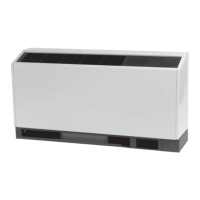
5. Mounting of the receptacle box (option) should be
made prior to piping and electrical hook-up. This factory
disconnect option is designed to fit inside the end
pocket. Mount the receptacle box 2 in. above the top of
the subbase with four, #8-field supplied screws.
2"
(4)--#8 FIELD
PROVIDED
MOUNTING
DEVICE
RECEPTACLE BOX
(FACTORY OPTION)
SEE UNIT WIRE
DIAGRAM FOR
ELECTRICAL HOOK-UP
7 1/4"
15 3/4"
47 1/4"
or
62 1/4"
#10 FIELD
PROVIDE
MOUNTING
DEVICE
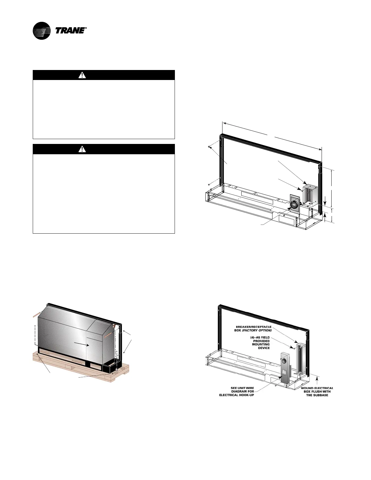
6. Mounting of the circuit breaker/receptacle box (option)
should be made prior to piping and electrical hook-up.
This factory disconnect option is designed to fit inside
the end pocket. Mount the electrical box flush with the
subbase with four, #8-field supplied screws.
7. Wiring of receptacle box (option). Power wiring to the
equipment should be installed per national and local
electric codes by a professional electrician. Power
wiring to the receptacle box may be done at this time.
See the unit’s wiring schematic for field wiring.
Note: Factory recommendation: Unit’s receiving the
circuit breaker option should have water and
condensate piping supplied/returned through the
bottom of the unit OR include the extended
cabinet option.