138
RT-SVX072A-EN
WWAARRNNIINNGG
HHaazzaarrddoouuss VVoollttaaggee ww//CCaappaacciittoorrss!!
FFaaiilluurree ttoo ddiissccoonnnneecctt ppoowweerr aanndd ddiisscchhaarrggee
ccaappaacciittoorrss bbeeffoorree sseerrvviicciinngg ccoouulldd rreessuulltt iinn ddeeaatthh oorr
sseerriioouuss iinnjjuurryy..
DDiissccoonnnneecctt aallll eelleeccttrriicc ppoowweerr,, iinncclluuddiinngg rreemmoottee
ddiissccoonnnneeccttss aanndd ddiisscchhaarrggee aallll mmoottoorr ssttaarrtt//rruunn
ccaappaacciittoorrss bbeeffoorree sseerrvviicciinngg.. FFoollllooww pprrooppeerr
lloocckkoouutt//ttaaggoouutt pprroocceedduurreess ttoo eennssuurree tthhee ppoowweerr
ccaannnnoott bbee iinnaaddvveerrtteennttllyy eenneerrggiizzeedd.. FFoorr vvaarriiaabbllee
ffrreeqquueennccyy ddrriivveess oorr ootthheerr eenneerrggyy ssttoorriinngg
ccoommppoonneennttss pprroovviiddeedd bbyy TTrraannee oorr ootthheerrss,, rreeffeerr ttoo
tthhee aapppprroopprriiaattee mmaannuuffaaccttuurreerr’’ss lliitteerraattuurree ffoorr
aalllloowwaabbllee wwaaiittiinngg ppeerriiooddss ffoorr ddiisscchhaarrggee ooff
ccaappaacciittoorrss.. VVeerriiffyy wwiitthh aa CCAATT IIIIII oorr IIVV vvoollttmmeetteerr
rraatteedd ppeerr NNFFPPAA 7700EE tthhaatt aallll ccaappaacciittoorrss hhaavvee
ddiisscchhaarrggeedd..
1. To determine the appropriate belt deflection:
a. Measure the center-to-center distance, in
inches, between the fan sheave and the motor
sheave.
b. Divide the distance measured in Step 1a by 64;
the resulting value represents the amount of
belt deflection for the proper belt tension.
2. Set the large O-ring on the belt tension gauge at the
deflection value determined in Step 1b.
3. Set the small O-ring at zero on the force scale of the
gauge.
4. Place the large end of the gauge on the belt at the
center of the belt span. Depress the gauge plunger
until the large O-ring is even with the of the second
belt or even with a straightedge placed across the
sheaves.
5. Remove the tension gauge from the belt. Notice
that the small O-ring now indicates a value other
than zero on the force scale. This value represents
the force (in pounds) required to deflect the belt(s)
the proper distance when properly adjusted.
6. Compare the force scale reading in step 5 with the
appropriate “force” value in Table 66, p. 138. If the
force reading is outside of the listed range for the
type of belts used, either readjust the belt tension or
contact a qualified service representative.
NNoottee:: The actual belt deflection force must not
exceed the maximum value shown in Table
66, p. 138 .
7. Recheck the new belt's tension at least twice during
the first 2 to 3 days of operation. Readjust the belt
tension as necessary to correct for any stretching
that may have occurred. Until the new belts are
“run in”, the belt tension will decrease rapidly as
they stretch.
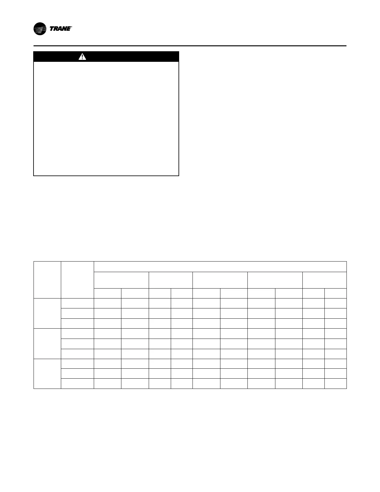
Table 66. Belt tension measurements and deflection forces
Belts
Cross
Section
Small P.D
Range
Deflection Force (Lbs.)
Super Gripbelts Gripnotch
Steel Cable
Gripbelts 358 Gripbelts
358 Gripnotch
Belts
Min. Max. Min. Max. Min. Max. Min. Max. Min. Max.
A
3.0 -3.6 3
4 1/2 3 7/8 5 1/2 3 1/4
4 — — — —
3.8 - 4.8
3 1/2
5
4 1/2 6 1/4 3 3/4 4 3/4
— — — —
5.0 - 7.0 4
5 1/2
5
6 7/8 4 1/4 5 1/4
— — — —
B
3.4 - 4.2 4
5 1/2 5 3/4
8
4 1/2 5 1/2
— — — —
4.4 - 5.6
5 1/8 7 1/8 6 1/2 9 1/8 5 3/4 7 1/4
— — — —
5.8 - 8.8
6 3/8 8 3/4 7 3/8 10 1/8
7
8 3/4
— — — —
5V
4.4 - 8.7 — — — — — — — — 10 15
7.1 - 10.9 — — — — — —
10 1/2 15 3/4 12 7/8 18 3/4
11.8 - 16.0 — — — — — — 13
19 1/2
15 22
Scroll Compressor Replacement
The compressor manifold system was purposely
designed to provide proper oil return to each
compressor. The refrigerant manifold system must not
be modified in any way.
NNoottee:: Altering the compressor manifold piping may
cause oil return problems and compressor
failure.
Should a compressor replacement become necessary
and a suction line filter drier is to be installed, install it a
minimum of 16 or 25 inches upstream of the oil
separator tee. See Figure 110, p. 139.
SSeerrvviiccee aanndd MMaaiinntteennaannccee

 Loading...


