RT-SVX072A-EN
51
NNoottee:: Each power supply must be protected from short
circuit and ground fault conditions. To comply
with NEC, protection devices must be sized
according to the “Maximum Over current
Protection” (MOP) or “Recommended Dual
Element” (RDE) fuse size data on the unit
nameplate.
Provide grounding for the supply power circuit in the
electric heat control box.
Main Unit Power Wiring
to lists the field connection wire ranges for both the
main power terminal block (2XD1 on 20-75T units /
1XD1 on 90-130T units) and the optional main power
disconnect switch (2QB1 on 20-75T units / 1QB1 on 90-
130T units). Service Sizing Data lists the component
electrical data.
The electrical service must be protected from over
current and short circuit conditions in accordance with
NEC requirements. Protection devices must be sized
according to the electrical data on the nameplate. Refer
to the equations listed in the product catalog to
determine the following:
• the appropriate electrical service wire size based on
“Minimum Circuit Ampacity” (MCA)
• the “Maximum Over Current Protection” (MOP)
device
• the “Recommended Dual Element fuse size” (RDE)
WWAARRNNIINNGG
PPrrooppeerr FFiieelldd WWiirriinngg aanndd GGrroouunnddiinngg
RReeqquuiirreedd!!
FFaaiilluurree ttoo ffoollllooww ccooddee ccoouulldd rreessuulltt iinn ddeeaatthh oorr
sseerriioouuss iinnjjuurryy..
AAllll ffiieelldd wwiirriinngg MMUUSSTT bbee ppeerrffoorrmmeedd bbyy qquuaalliiffiieedd
ppeerrssoonnnneell.. IImmpprrooppeerrllyy iinnssttaalllleedd aanndd ggrroouunnddeedd
ffiieelldd wwiirriinngg ppoosseess FFIIRREE aanndd EELLEECCTTRROOCCUUTTIIOONN
hhaazzaarrddss.. TToo aavvooiidd tthheessee hhaazzaarrddss,, yyoouu MMUUSSTT ffoollllooww
rreeqquuiirreemmeennttss ffoorr ffiieelldd wwiirriinngg iinnssttaallllaattiioonn aanndd
ggrroouunnddiinngg aass ddeessccrriibbeedd iinn NNEECC aanndd yyoouurr llooccaall//
ssttaattee//nnaattiioonnaall eelleeccttrriiccaall ccooddeess..
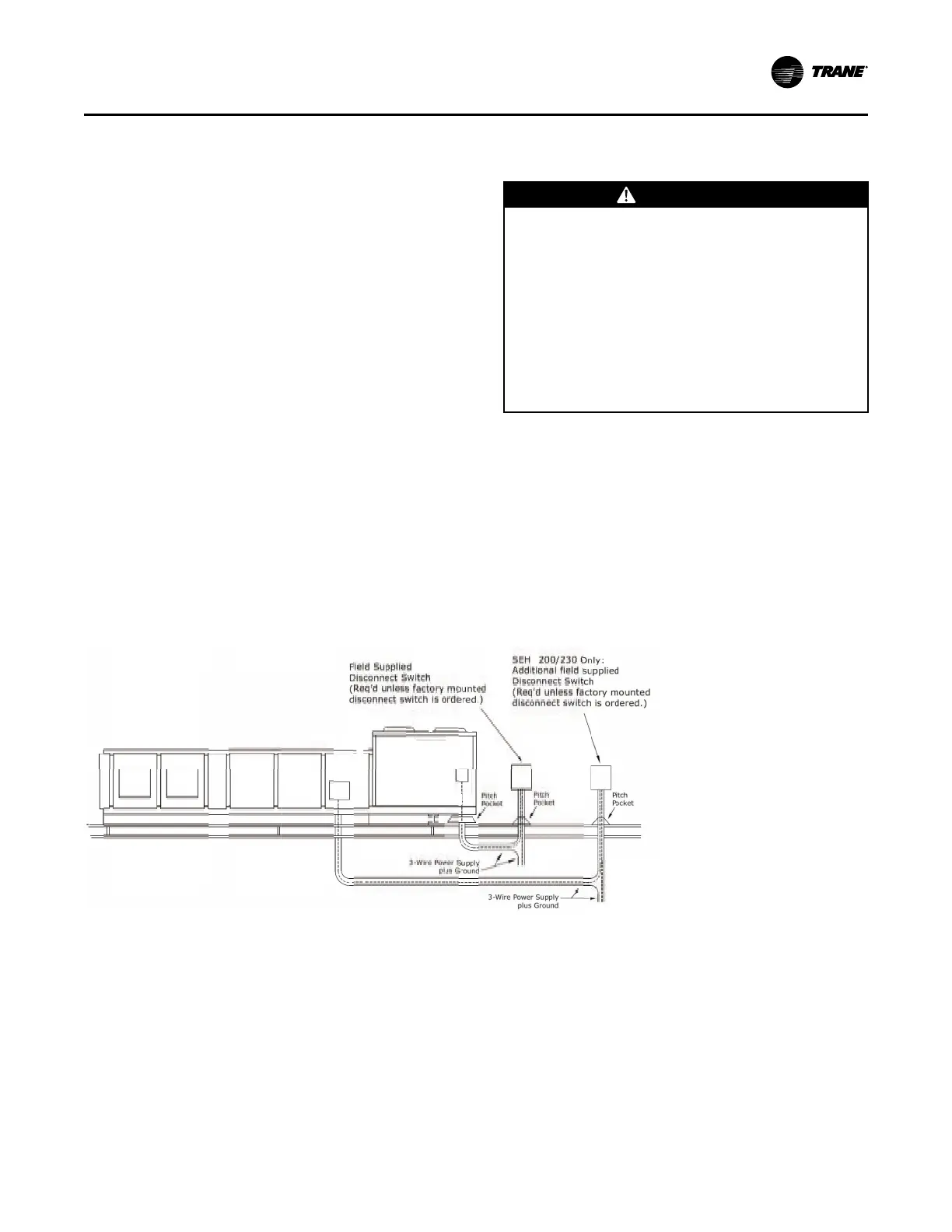
The location of the electrical service entrance is
illustrated in . It is important to complete the unit
power wiring connections onto either the main
terminal block (2XD1 on 20-75T units / 1XD1 on 90-130T
units) or the factory mounted, non-fused disconnect
switch (2XD1 on 20-75T units / 1XD1 on 90-130T units).
. Refer to the diagrams that shipped with the unit for
specific termination points.
Provide proper grounding for the unit in accordance
with local and national codes.
Figure 31. Typical field power wiring (20 to 75 ton)
IInnssttaallllaattiioonn

 Loading...


