50
RT-SVX072A-EN
shackle can be placed between the handle and the
thumb key, locks the handle so the unit cannot be
energized. Turning the handle to this position also
releases the handle from the disconnect switch,
allowing the control panel door to be opened.
WWAARRNNIINNGG
HHaazzaarrddoouuss VVoollttaaggee ww//CCaappaacciittoorrss!!
FFaaiilluurree ttoo ddiissccoonnnneecctt ppoowweerr aanndd ddiisscchhaarrggee
ccaappaacciittoorrss bbeeffoorree sseerrvviicciinngg ccoouulldd rreessuulltt iinn ddeeaatthh oorr
sseerriioouuss iinnjjuurryy..
DDiissccoonnnneecctt aallll eelleeccttrriicc ppoowweerr,, iinncclluuddiinngg rreemmoottee
ddiissccoonnnneeccttss aanndd ddiisscchhaarrggee aallll mmoottoorr ssttaarrtt//rruunn
ccaappaacciittoorrss bbeeffoorree sseerrvviicciinngg.. FFoollllooww pprrooppeerr
lloocckkoouutt//ttaaggoouutt pprroocceedduurreess ttoo eennssuurree tthhee ppoowweerr
ccaannnnoott bbee iinnaaddvveerrtteennttllyy eenneerrggiizzeedd.. FFoorr vvaarriiaabbllee
ffrreeqquueennccyy ddrriivveess oorr ootthheerr eenneerrggyy ssttoorriinngg
ccoommppoonneennttss pprroovviiddeedd bbyy TTrraannee oorr ootthheerrss,, rreeffeerr ttoo
tthhee aapppprroopprriiaattee mmaannuuffaaccttuurreerr’’ss lliitteerraattuurree ffoorr
aalllloowwaabbllee wwaaiittiinngg ppeerriiooddss ffoorr ddiisscchhaarrggee ooff
ccaappaacciittoorrss.. VVeerriiffyy wwiitthh aa CCAATT IIIIII oorr IIVV vvoollttmmeetteerr
rraatteedd ppeerr NNFFPPAA 7700EE tthhaatt aallll ccaappaacciittoorrss hhaavvee
ddiisscchhaarrggeedd..
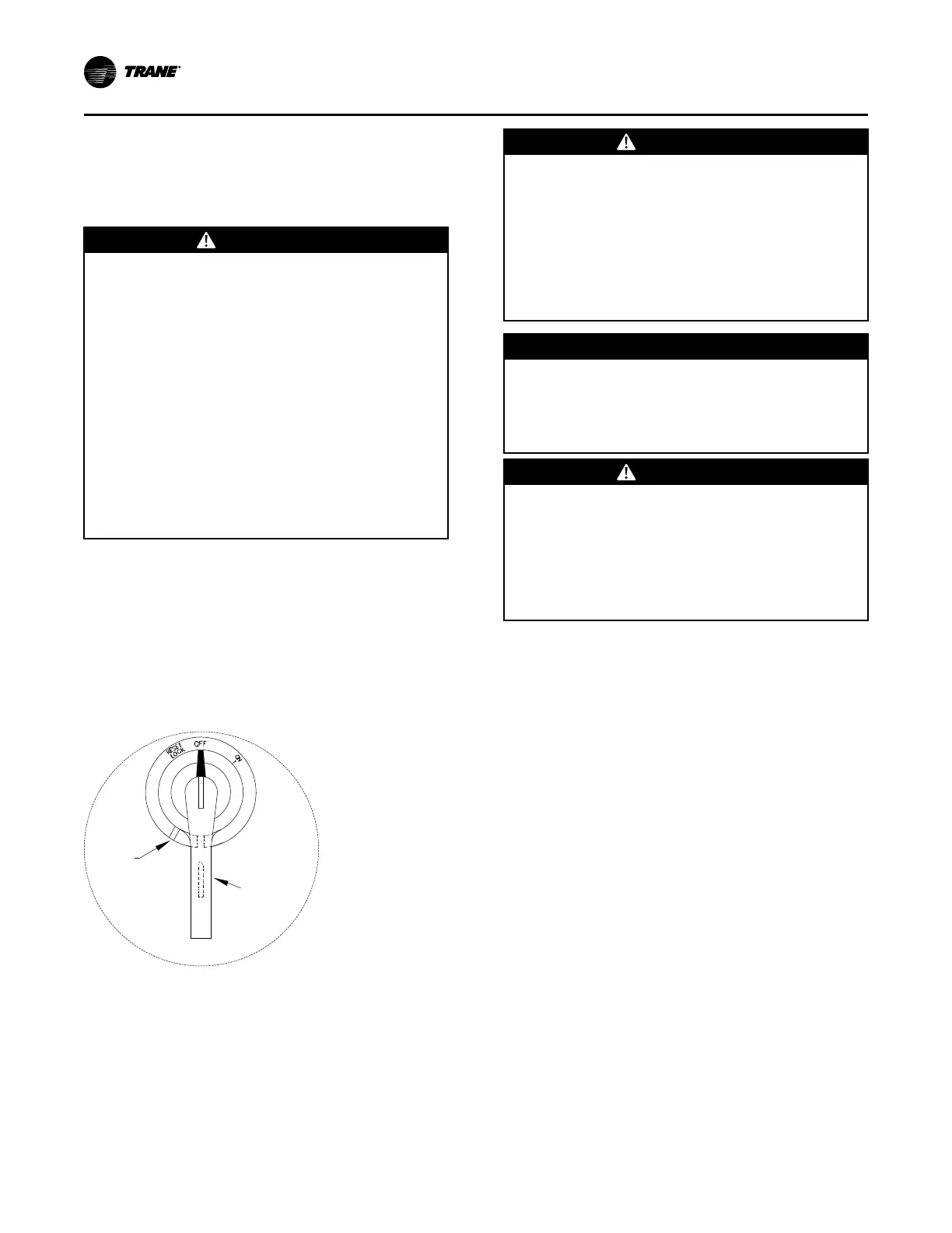
The handle can be locked in the “OFF” position by
completing the following steps (see Figure 30, p. 50):
1. While holding the handle in the “OFF” position,
push the spring loaded thumb key, attached to the
handle, into the base slot.
2. Place the lock shackle between the handle and the
thumb key. This will prevent it from springing out of
position.
Figure 30. Disconnect switch external handle
Locking
Slot
Locking
Thumb
Key Under
Handle
NNoottee:: All field installed wiring must conform to NEC
guidelines as well as State and Local codes.
An overall layout of the field required power wiring is
illustrated in . To ensure that the unit supply power
wiring is properly sized and installed, follow these
guidelines:
WWAARRNNIINNGG
LLiivvee EElleeccttrriiccaall CCoommppoonneennttss!!
FFaaiilluurree ttoo ffoollllooww aallll eelleeccttrriiccaall ssaaffeettyy pprreeccaauuttiioonnss
wwhheenn eexxppoosseedd ttoo lliivvee eelleeccttrriiccaall ccoommppoonneennttss ccoouulldd
rreessuulltt iinn ddeeaatthh oorr sseerriioouuss iinnjjuurryy..
WWhheenn iitt iiss nneecceessssaarryy ttoo wwoorrkk wwiitthh lliivvee eelleeccttrriiccaall
ccoommppoonneennttss,, hhaavvee aa qquuaalliiffiieedd lliicceennsseedd eelleeccttrriicciiaann
oorr ootthheerr iinnddiivviidduuaall wwhhoo hhaass bbeeeenn pprrooppeerrllyy ttrraaiinneedd
iinn hhaannddlliinngg lliivvee eelleeccttrriiccaall ccoommppoonneennttss ppeerrffoorrmm
tthheessee ttaasskkss..
NNOOTTIICCEE
UUssee CCooppppeerr CCoonndduuccttoorrss OOnnllyy!!
FFaaiilluurree ttoo uussee ccooppppeerr ccoonndduuccttoorrss ccoouulldd rreessuulltt iinn
eeqquuiippmmeenntt ddaammaaggee aass tthhee eeqquuiippmmeenntt wwaass nnoott
ddeessiiggnneedd oorr qquuaalliiffiieedd ttoo aacccceepptt ootthheerr ttyyppeess ooff
ccoonndduuccttoorrss..
WWAARRNNIINNGG
HHoott SSuurrffaaccee!!
FFaaiilluurree ttoo ffoollllooww iinnssttrruuccttiioonnss bbeellooww ccoouulldd rreessuulltt iinn
sseevveerree bbuurrnnss..
DDoo nnoott ttoouucchh tthhee hheeaatt eexxcchhaannggeerr bbooaarrdd wwiitthh bbaarree
hhaannddss wwhhiillee ddiissaasssseemmbblliinngg tthhee ppaann.. AAllllooww ttoo ccooooll
aanndd ppuutt oonn pprrooppeerr PPeerrssoonnaall PPrrootteeccttiivvee EEqquuiippmmeenntt
((PPPPEE)) bbeeffoorree sseerrvviicciinngg..
• Verify that the power supply available is compatible
with the unit nameplate rating for all components.
The available power supply must be within 10% of
the rated voltage stamped on the nameplate.
• Use only copper conductors to connect the 3-phase
power supply to the unit.
Electric Heat Units (SEH_)
SEH_ (20-75 ton) electric heat units operating on 200/
230 volts require two power supplies as illustrated in .
Unless the unit was ordered with the optional factory
mounted, non-fused disconnect switches, two field-
supplied disconnect switches must be installed per
NEC requirements. The power wires for the electric
heat are routed into the electric heat control panel
using the through-the-base access provided in the
heating section. Refer to the appropriate illustration in ,
(unit base layout and electrical entrance diagram), for
dimensional data. For 20-130 ton units operating on
460/575 volts, only one field installed disconnect switch
is required, as illustrated in and .
Use the information provided in Service Sizing data
and the “Power Wire Sizing & Protection Device
Equations,” to determine the appropriate wire size and
Maximum Over current Protection for the heaters/unit.
IInnssttaallllaattiioonn

 Loading...


