30
RT-SVX072A-EN
Installation
Roof Curb and Ductwork
The roof curbs consist of two main components: a
pedestal to support the unit condenser section and a
“full perimeter” enclosure to support the unit’s air
handler section.
Before installing any roof curb, verify the following:
• It is the correct curb for the unit.
• It includes the necessary gaskets and hardware.
• The purposed installation location provides the
required clearance for proper operation.
• The curb is level and square — the top surface of
the curb must be true to assure an adequate curb-
to-unit seal.
Step-by-step curb assembly and installation
instructions ship with each Trane accessory roof curb
kit. Follow the instructions carefully to assure proper
fit-up when the unit is set into place.
NNoottee:: To assure proper condensate flow during
operation, the unit (and curb) must be as level as
possible. The maximum slope allowable for
rooftop unit applicationsexcluding SSH_s, is 4"
end-to-end and 2" side-to-side. Units with steam
coils (SSH_s) must be set level!
If the unit is elevated, a field constructed catwalk
around the unit is strongly recommended to provide
easy access for unit maintenance and service.
Recommendations for installing the Supply Air and
Return Air ductwork joining the roof curb are included
in the curb instruction booklet. Curb ductwork must be
fabricated and installed by the installing contractor
before the unit is set into place.
NNoottee:: For sound consideration, cut only the holes in the
roof deck for the ductwork penetrations. Do not
cut out the entire roof deck within the curb
perimeter.
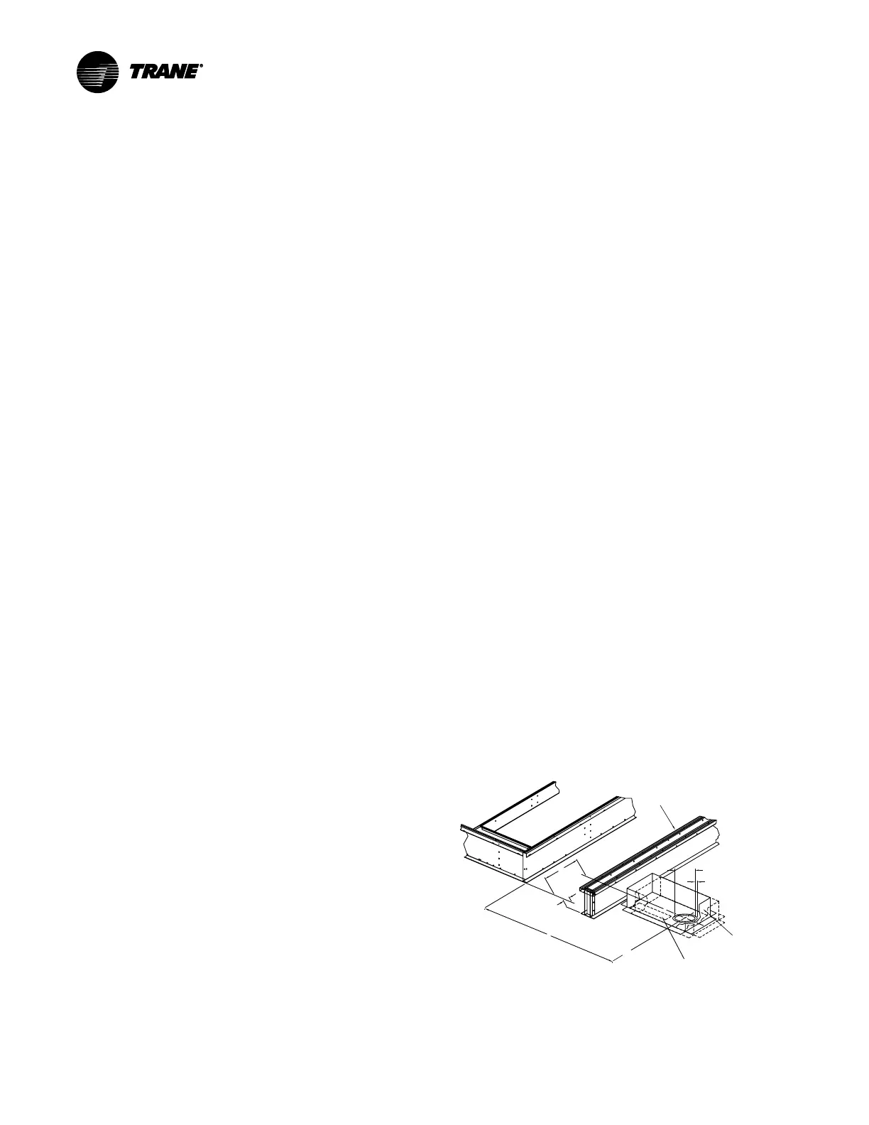
Pitch Pocket Location
The location of the main supply power entry is located
at the bottom right-hand corner of the control panel.
illustrates the location for the electrical entrance
through the base in order to enter the control panel. If
the power supply conduit penetrates the building roof
beneath this opening, it is recommended that a pitch
pocket be installed before the unit is placed onto the
roof curb.
The center line dimensions shown in the illustration
below indicates the center line of the electrical access
hole in the unit base when it is positioned on the curb,
±3/8 inch. The actual diameter of the hole in the roof
should be at least 1/2 inch larger than the diameter of
the conduit penetrating the roof. This will allow for the
clearance variable between the roof curb rail and the
unit base rail illustrated in Figure 10, p. 30.
The pitch pocket dimensions listed are recommended
to enhance the application of roofing pitch after the
unit is set into place. The pitch pocket may need to be
shifted as illustrated to prevent interference with the
curb pedestal.
If a Trane Curb Accessory Kit is not used:
• The ductwork can be attached directly to the
factory-provided flanges around the unit supply
and return air openings. Be sure to use flexible duct
connections at the unit.
• For “built-up” curbs supplied by others, gaskets
must be installed around the curb perimeter flange
and the supply and return air opening flanges.
• If a “built-up” curb is provided by others, it should
NOT be made of wood.
• If a “built-up” curb is provided by others, keep in
mind that these commercial rooftop units do not
have base pans in the condenser section.
• If this is a REPLACEMENT UNIT without the IRU
option, keep in mind that the CURRENT DESIGN
commercial rooftop units do not have base pans in
the condenser section.
• Trane roof curbs are recommended. If using a non-
Trane roof curb with right-angle return airflow
approaches to a return fan inlet, a rigid, solid flow
baffle wall should be installed across the full width
of the roof curb return airflow path in the position
shown in Figure 16, p. 37 to reduce potential
airflow disturbances at the return fan inlet that
could contribute to unusual return fan noise.
• If a full perimeter curb is used, make sure the IRU
option was added to the unit to ensure stability in
the condenser section
Figure 10. Pitch pocket location
S
upply Air Opening
Pedestal
Conduit Diameter
Roof Curb
Cut-a-Way
4-13/16”
1/2” Clearance
Pitch Pocket
16” x 8”
*Control Wire Conduit
Access Area (Illustration Only)
C
L
C
B
A
L

 Loading...


