RT-SVX072A-EN
63
Main Electrical Power
Lock and tag out unit main electric power and remove
power supply wiring from installed disconnect/terminal
block of unit. See for locations.
NNoottee:: Inspect wiring to ensure that all field-installed
wiring complies with NEC and applicable local
codes.
SEHF Units with 200V or 230V Electric
Heat
(Requires separate power supply to heater)
Lock and tag out unit main electric power and remove
power supply wiring for the electric heat from a
dedicated, field- supplied/installed disconnect to
terminal block, or to an optional unit-mounted
disconnect switch. See for locations.
Field-installed Control Wiring
NNoottee:: Inspect wiring to ensure that all field-installed
wiring complies with NEC and applicable local
codes.
Remove the field wiring connections for the variable air
volume controls as applicable.
NNoottee:: Label wiring to save time when reconnecting
wiring is necessary.
Remove ground wire from the unit.
NNoottee:: The electrical connection for 40, 60, 70 and 75 ton
is 32 inches further down the unit than older
(pre-2010) style units. On full perimeter curbs,
this also means the incoming electrical will be
outside the curb area. The electrician should be
informed of both points.
See for typical field wiring for 20-75 ton units. See
Figure 32, p. 52 for typical field power wiring for 90-130
ton units.
Requirements for Gas Heat
WWAARRNNIINNGG
HHaazzaarrddoouuss GGaasseess aanndd FFllaammmmaabbllee
VVaappoorrss!!
FFaaiilluurree ttoo oobbsseerrvvee tthhee ffoolllloowwiinngg iinnssttrruuccttiioonnss ccoouulldd
rreessuulltt iinn eexxppoossuurree ttoo hhaazzaarrddoouuss ggaasseess,, ffuueell
ssuubbssttaanncceess,, oorr ssuubbssttaanncceess ffrroomm iinnccoommpplleettee
ccoommbbuussttiioonn,, wwhhiicchh ccoouulldd rreessuulltt iinn ddeeaatthh oorr sseerriioouuss
iinnjjuurryy.. TThhee ssttaattee ooff CCaalliiffoorrnniiaa hhaass ddeetteerrmmiinneedd tthhaatt
tthheessee ssuubbssttaanncceess mmaayy ccaauussee ccaanncceerr,, bbiirrtthh ddeeffeeccttss,,
oorr ootthheerr rreepprroodduuccttiivvee hhaarrmm..
IImmpprrooppeerr iinnssttaallllaattiioonn,, aaddjjuussttmmeenntt,, aalltteerraattiioonn,,
sseerrvviiccee oorr uussee ooff tthhiiss pprroodduucctt ccoouulldd ccaauussee
ffllaammmmaabbllee mmiixxttuurreess oorr lleeaadd ttoo eexxcceessssiivvee ccaarrbboonn
mmoonnooxxiiddee.. TToo aavvooiidd hhaazzaarrddoouuss ggaasseess aanndd
ffllaammmmaabbllee vvaappoorrss ffoollllooww pprrooppeerr iinnssttaallllaattiioonn aanndd
sseettuupp ooff tthhiiss pprroodduucctt aanndd aallll wwaarrnniinnggss aass pprroovviiddeedd
iinn tthhiiss mmaannuuaall..
1. Remove and isolate gas supply from the unit gas
train.
2. Ensure gas supply line piping joints are properly
sealed.
3. Remove drip leg Installed in the gas piping near the
unit.
4. Remove factory-supplied flue assembly installed on
the unit.
5. Remove the 3/4" CPVC furnace drain stub out that
was used for condensate drain.
Requirements for Hot Water Heat (SLH*)
1. Remove and isolate water piping that comes into
the heating section from the base of the unit.
2. Remove the installed, 3-way modulating valve, if
necessary, to remove unit.
3. Remove the valve actuator wiring.
Requirements for Steam Heat (SSH*)
1. Remove and isolate steam piping that comes into
the heating section from the base of the unit.
2. Remove, 2-way modulating valve if necessary.
3. Remove the valve actuator wiring.
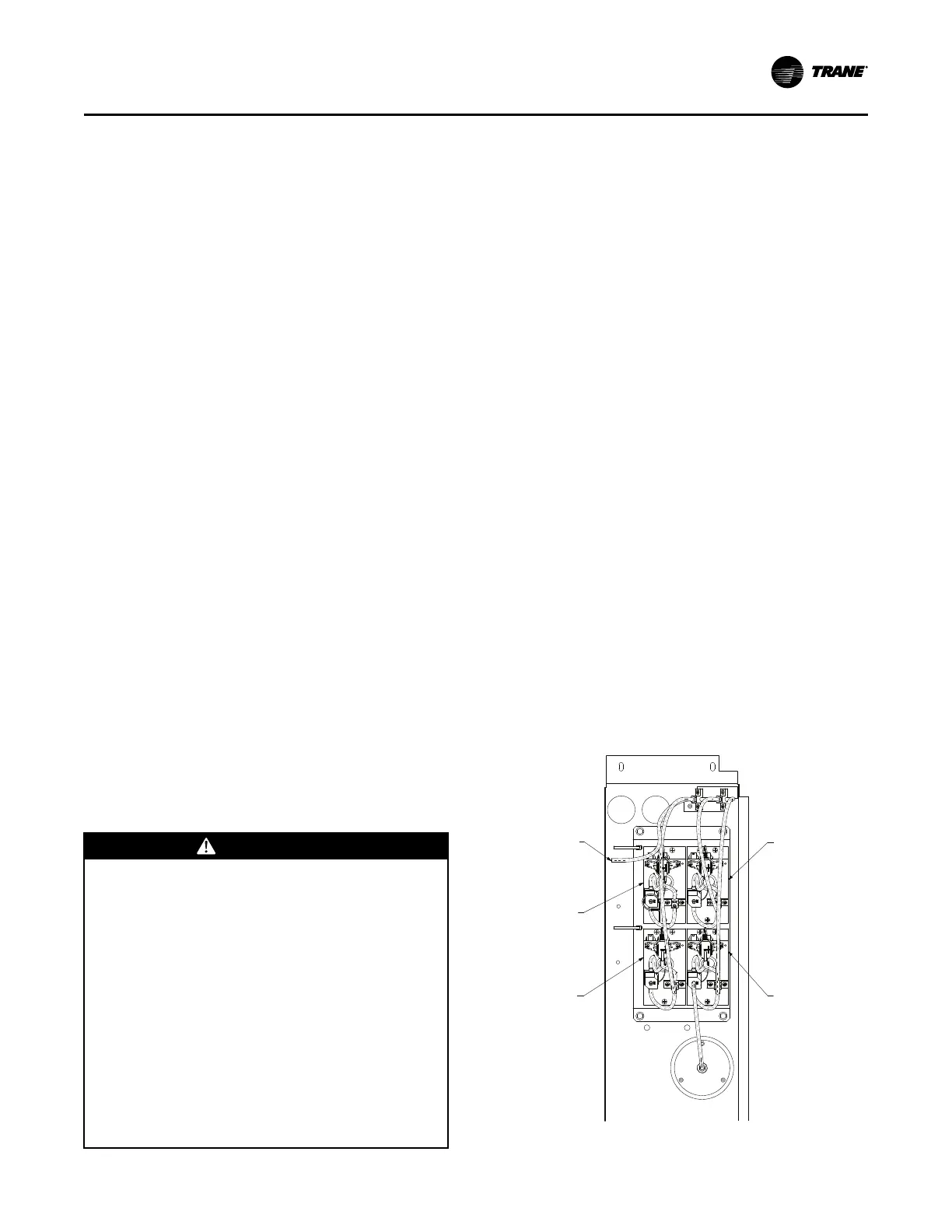
Space Pressure Sensor and Tubing
Installation
(All units with Statitrac)
Remove field-supplied pneumatic tubing connected to
the space pressure transducer located in the filter
section (see Figure 33, p. 63).
Figure 33. Duct static pressure control layout
SPACE PRESSURE TRANSDUCER
& SOLENOID ASSEMBLY
DUCT STATIC
TRANSDUCER ASSEMBLY
OUTSIDE AIR REFERENCE
TUBE CONNECTS HERE
RETURN AIR TRANSDUCER
& SOLENOID ASSEMBLY
TRAQ TRANSDUCER
& SOLENOID ASSEMBLY
UUnniitt RReeppllaacceemmeenntt

 Loading...


