18-GJ89D1-1F-EN
37
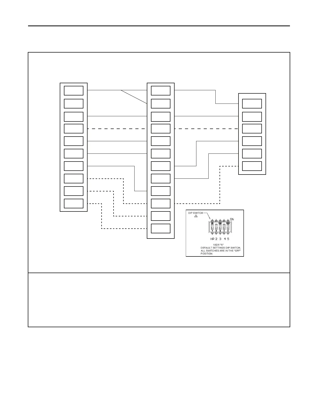
Table 21. 24 Volt Low Voltage Wiring
COMFORT CONTROL
R
BK
B/C
O
Y1
Y2
G
W1
W2
W3
OUTDOOR UNIT
R
B
O
Y1
Y2
X2
INDOOR UNIT
R
BK
B
O
Y1in
Y2in
Y1out
Y2out
G
W1
W2
W3
2 Stage Cooling or Heat Pump with TAMX Variable Speed Air Handler
Note 1
Note 3
Note 5
Note 2
Note 4
Note 6
For AC only units, move dip switch 1 to the ON position.*
*if not using tech app for configuration.
Notes:
1. Separate the BK and R wires when using the BK functionality from the thermostat or a Humidistat.
2. Yin and Yout connections must be made as shown for freeze protection and internally mounted condensate overflow circuits to
function properly.
3. 3rd party condensate switch should break the Y1-in circuit between the thermostat and AHC.
4. Y2-out connections at outdoor unit only required for two stage units and should be capped off when not in use.
5. Only needed for heat pump operation.
6. X2 is necessary if not using select Trane or American Standard thermostats.
EElleeccttrriiccaall —— LLooww VVoollttaaggee