38
18-GJ89D1-1F-EN
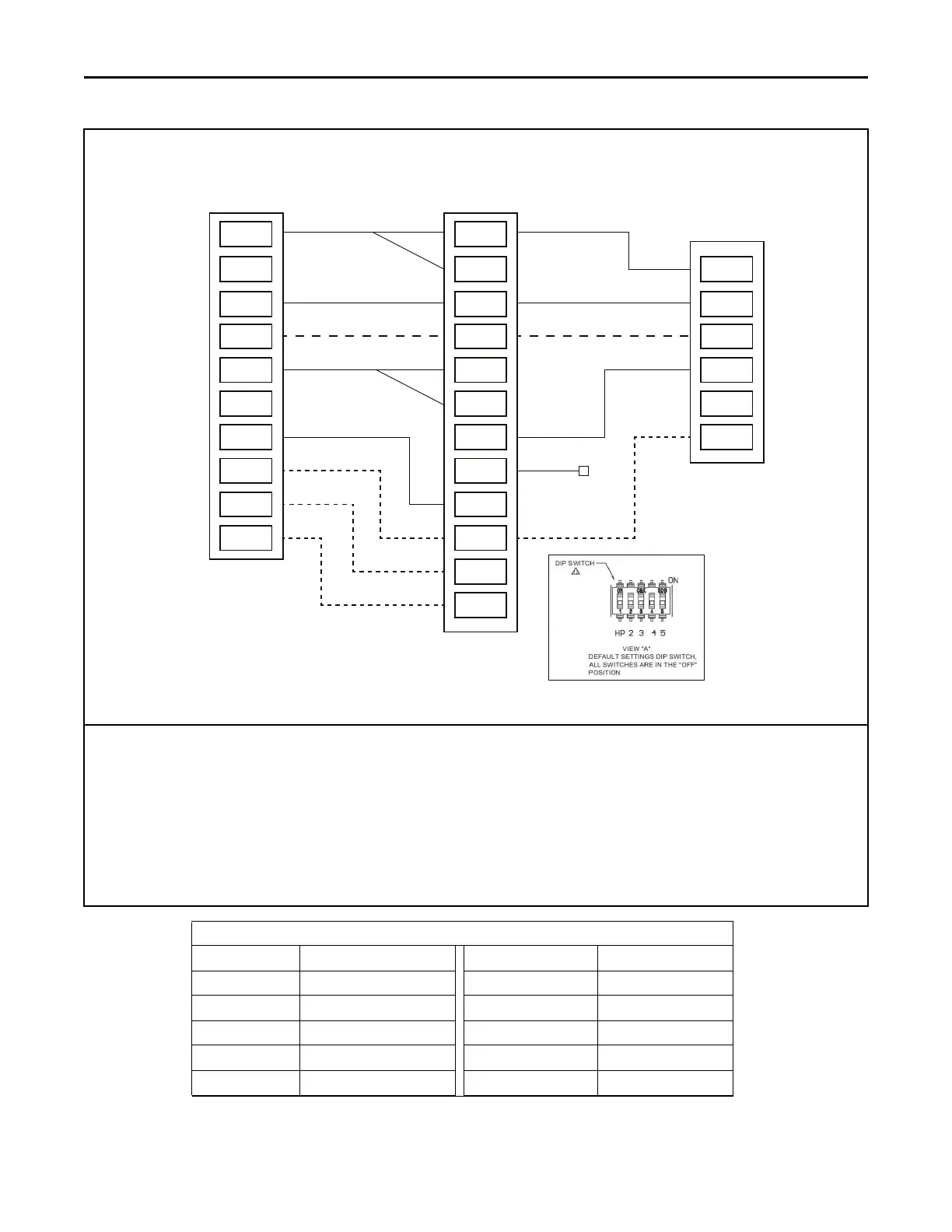
COMFORT CONTROL
R
BK
B/C
O
Y1
Y2
G
W1
W2
W3
OUTDOOR UNIT
R
B
O
Y1
Y2
X2
INDOOR UNIT
R
Note 1
Note 6
Note 4
Note 5
Note 2
Note 3 & Note 7
BK
B
O
Y1-in
Y2-in
Y1-out
Y2-out
G
W1
W2
W3
1 Stage Cooling or Heat Pump with TAMX Variable Speed Air Handler
For AC only units, move dip switch 1 to the ON position.*
*if not using tech app for configuration.
Notes:
1. Separate the BK and R wires when using the BK functionality from the thermostat or a Humidistat.
2. Y-in and Y-out connections must be made as shown for freeze protection and internally mounted condensate overflow circuits to
function properly.
3. 3rd party condensate switch should break the Y1-in circuit between the thermostat and AHC.
4. X2 is necessary if not using select Trane or American Standard thermostats.
5. For single speed operation, use Y1-out and cap off Y2-out wire.
6. Only needed for heat pump operation.
7. For single stage outdoor operation, must connect Y1–in and Y2–in for full airflow.
TAMX 24 Volt Wire Harness Colors
R Red Y2out Orange/Red
B Blue G Green
O Orange BK Black
Y1in Yellow W1 White
Y2in Yellow/Red W2 White/Black
Y1out Yellow/ Black W3 White/Red
EElleeccttrriiccaall —— LLooww VVoollttaaggee