8 I-Frame Size Disassembly and Assembly Procedures
8.1 General Disassembly Procedure
This procedure explains how to remove the outer parts of
the frequency converter that are common for all I-frame
sizes. When this procedure is completed, the inside
components are accessible.
1. Loosen and remove the 4 screws (T20) from the
front cover.
2. Remove the front cover.
3. Remove the screw and sheet metal next to the
EMC shield.
4. Loosen and remove the 4 screws (T20) from the
cable entry.
5. Remove the cable entry.
8.2 I6 Frame Size Disassembly and
Assembly Instructions
8.2.1 Control Card and Control Card
Mounting Plate
1. Remove LCP cradle.
2. Remove 3 screws (T12) on the control board.
3. Remove the control board.
4. Remove 1 screw (T20) on the fan bracket.
5. Unplug the fan cable and remove the fan.
6. Remove 4 screws (T20) on the control card
mounting plate.
7. Unplug ribbon cable.
8. Remove control card mounting plate.
Reinstall in the reverse order.
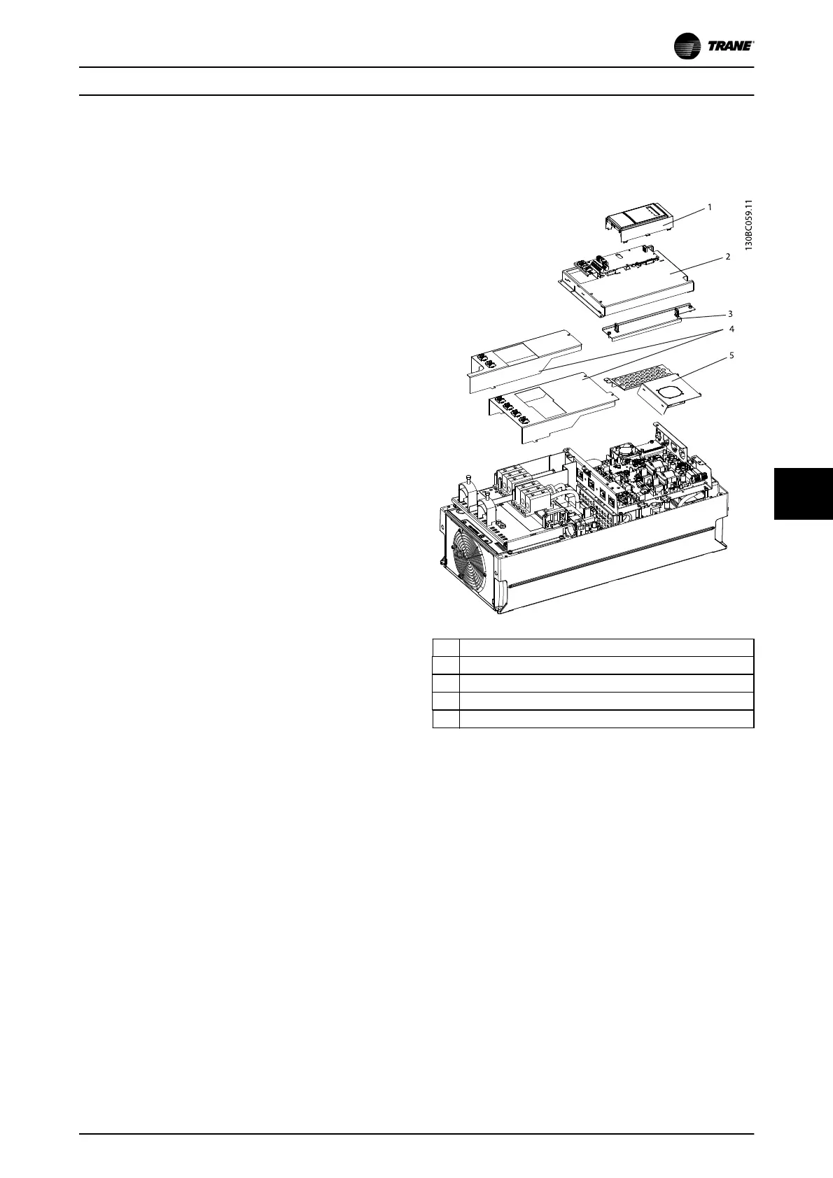
1LCP and cradle
2 Control card and mounting plate
3 Support bracket
4Terminal plates
5EMC shield
Illustration 8.1 Control Card and Control Card Mounting Plate
I-Frame Size Disassembly an... TR150 and TR170 Service Manual
BAS-SVM04B-EN 02/2017 All rights reserved. 75
8