CTV-SVU01G-EN
85
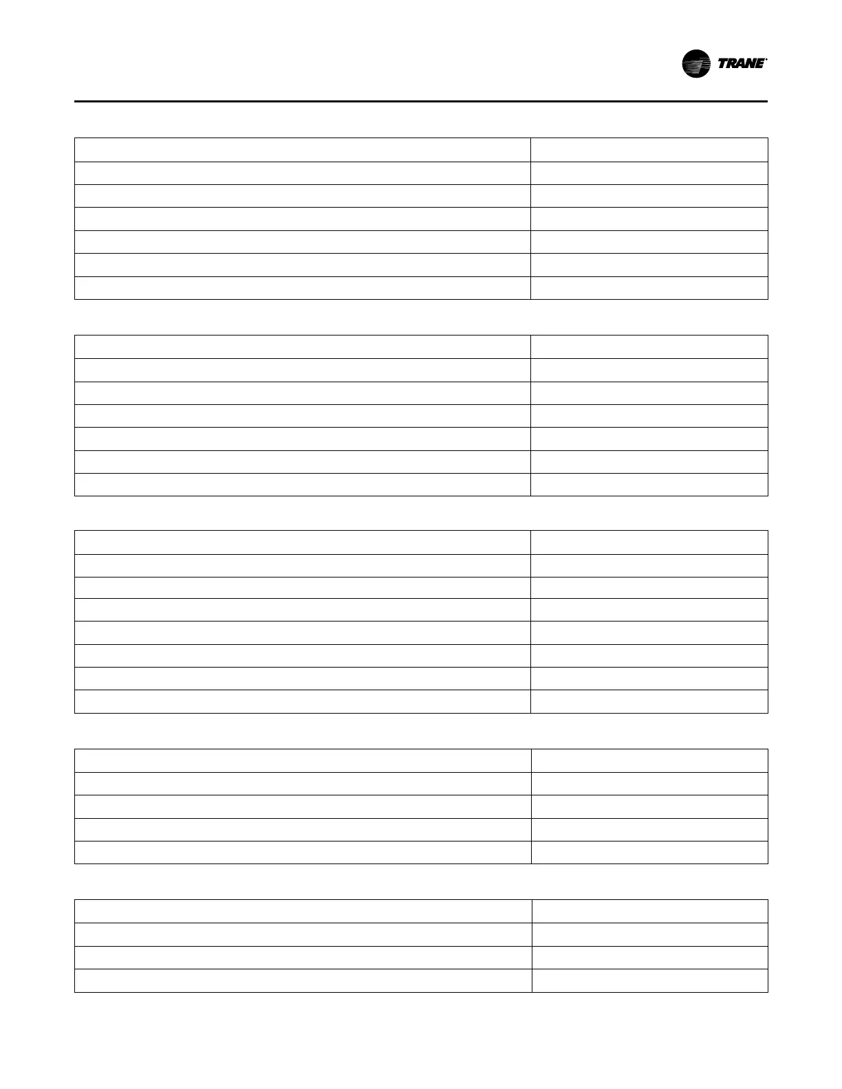
Table 70. Oil System
Graph data point
Axis
Oil Differential Pressure (Ckt1 and Ckt2)
Left Y-axis
Oil Tank Pressure (Ckt1 and Ckt2)
Left Y-axis
Oil Pump Discharge Pressure (Ckt1 and Ckt2)
Left Y-axis
Oil Tank Temperature (Ckt1 and Ckt2) Right Y-axis
Outboard Bearing Temperature (Ckt1 and Ckt2) Right Y-axis
Inboard Bearing Temperature (Ckt1 and Ckt2) Right Y-axis
Table 71. Oil System
Graph data point
Axis
Oil Differential Pressure (Ckt1 and Ckt2)
Left Y-axis
Oil Tank Pressure (Ckt1 and Ckt2)
Left Y-axis
Oil Pump Discharge Pressure (Ckt1 and Ckt2)
Left Y-axis
Oil Tank Temperature (Ckt1 and Ckt2) Right Y-axis
Outboard Bearing Temperature (Ckt1 and Ckt2) Right Y-axis
Inboard Bearing Temperature (Ckt1 and Ckt2) Right Y-axis
Table 72. Motor
Graph data point
Axis
Average Motor Current %RLA CktX
Left Y-axis
Starter Motor Current L1 % RLA CktX Left Y-axis
Starter Motor Current L2 % RLA (CktX)
Left Y-axis
Starter Motor Current L3 % RLA (CktX)
Left Y-axis
Starter Input Voltage Phase AB (CktX) Right Y-axis
Starter Input Voltage Phase BC (CktX) Right Y-axis
Starter Input Voltage Phase CA (CktX) Right Y-axis
Table 73. Motor Temperature
Graph data point
Axis
Motor Winding Temperature 1 (Ckt1 and Ckt2)
Left Y-axis
Motor Winding Temperature 2 (Ckt1 and Ckt2)
Left Y-axis
Motor Winding Temperature 3 (Ckt1 and Ckt2)
Left Y-axis
AFD Transistor Temperature (Ckt1 and Ckt2)
Left Y-axis
Table 74. Purge
Graph data point
Axis
Daily Pumpout—24 Hours (Ckt1 and Ckt2)
Left Y-axis
Pumpout Chiller On—7 Days (Ckt1 and Ckt2)
Left Y-axis
Pumpout Chiller Off—7 Days (Ckt1 and Ckt2)
Left Y-axis
AAppppeennddiixx BB:: DDaattaa ffoorr CCeennTTrraaVVaacc DDuupplleexx CChhiilllleerrss
 Loading...


