Configuration
CNT-SVX05B-EN 81
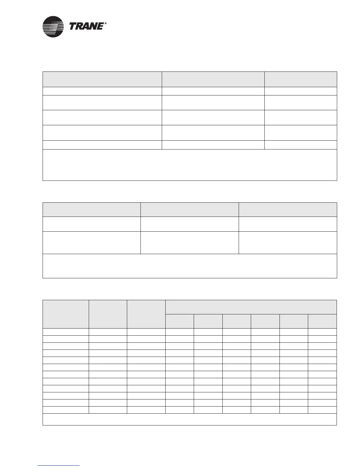
Table 53. Timer configuration
Parameter Valid range Default value
Power-up control wait 0 to 1000 seconds 300 seconds
Maintenance required time setpoint
(based on fan run hours)
0 to 10,000 hours 600 hours
Occupancy bypass timer
1
Space temperature control
0 to 240 minutes (1-minute resolution) 120 minutes
Occupancy bypass timer
1
Discharge air control
0 to 100% (1-minute resolution) 50%
Maximum heat delay
2
0 to 60 seconds 240 seconds (4 minutes)
1 The occupied bypass time is used for timed override applications when a building automation system is not present or when the
building automation system does not send the occupied (override) request. The timed override timer is maintained in the unit
controller. When the timed override is applicable, the controller reports Occupied Bypass as its effective occupancy mode.
2 Amount of time a variable-air-volume unit will delay electric heat operation on a transition from occupied to daytime warm-up
operation.
Table 54. Diagnostic alarm level configuration
Parameter Valid range Default value
Diagnostic alarm level
1
• Service required
• Critical alarm
Service required
Diagnostic language
2
• English
• Spanish
•French
English
1 Duct Static Pressure Failure, Duct Static Pressure High Limit, Space Temperature Failure, Discharge Air Temperature Failure, Unit
Shutdown, Low Temperature Detect, and Low Supply Fan Air Flow diagnostics can be configured as a group to be either service
required or critical alarm diagnostics; the diagnostics cannot be individually configured.
2 Alarm message text that will be communicated to the building automation system.
Table 55. Analog electric heat sequencer control configuration
Parameter
1
Range
Default
value
Default value
1 stage 2 stage 3 stage 4 stage 5 stage 6 stage
Stage 1 On 0 to 10 V 4.2 V 10.0 6.6 5.6 4.9 4.5 4.2
Stage 1 Off 0 to 10 V 0 V 0.0 0.0 0.0 0.0 0.0 0.0
Stage 2 On 0 to 10 V 5.2 V 10.0 10.0 7.4 6.4 5.7 5.2
Stage 2 Off 0 to 10 V 3.6 V 10.0 5.4 4.7 4.2 3.8 3.6
Stage 3 On 0 to 10 V 6.3 V 10.0 10.0 10.0 7.8 7.0 6.3
Stage 3 Off 0 to 10 V 4.7 V 10.0 10.0 6.4 5.6 5.1 4.7
Stage 4 On 0 to 10 V 7.4 V 10.0 10.0 10.0 10.0 8.2 7.4
Stage 4 Off 0 to 10 V 5.7 V 10.0 10.0 10.0 7.1 6.3 5.7
Stage 5 On 0 to 10 V 8.4 V 10.0 10.0 10.0 10.0 10.0 8.4
Stage 5 Off 0 to 10 V 6.8 V 10.0 10.0 10.0 10.0 7.5 6.8
Stage 6 On 0 to 10 V 10.0 V 10.0 10.0 10.0 10.0 10.0 10.0
Stage 6 Off 0 to 10 V 7.8 V 10.0 10.0 10.0 10.0 10.0 7.8
1 These set-up parameters are required for Tracer AH540/541 to properly stage electric heat when a step controller is connected
to analog output AO3. The controller assumes each stage On and Off voltage threshold matches the step controller setup.
 Loading...


