Chapter 5 Wiring inputs and outputs
22 CNT-SVN01C-EN
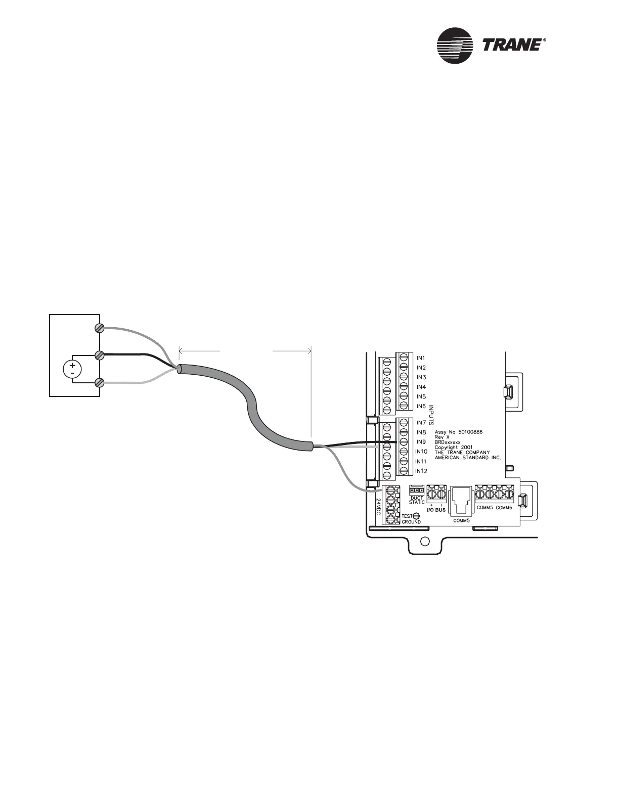
Wiring 0–10 Vdc analog inputs
Common 0–10 Vdc analog inputs include indoor air-quality sensors and
pressure sensors.
To wire a 0–10 Vdc analog input:
1. Use the shield wire as the common connection, connecting it to a com-
mon terminal at the sensor and at the termination board (see
Figure 13).
2. Connect the signal wire to an available input terminal (IN1–IN12).
3. Connect the supply wire to a 24 Vdc or 24 Vac terminal as required.
4. Use the Rover service tool to configure the input for analog operation.
Figure 13. Wiring a 0–10 Vdc analog input
< 300 ft
(100 m)
0–10 Vdc sensor
24 Vdc
0–10 Vdc out
Common
v

 Loading...


