LEDs on the EX2 expansion module
CNT-SVN01C-EN 83
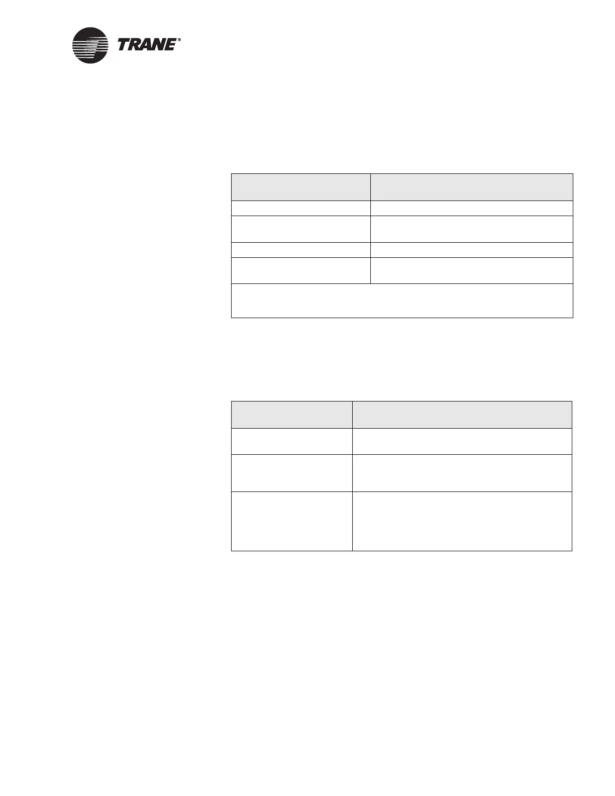
Status LED
The green Status LED indicates whether the controller has power applied
to it. Table 17 describes Status LED activity.
Comm LED
The yellow Comm LED indicates the communication status of the Tracer
MP581 controller. Table 18 describes Comm LED activity.
LEDs on the EX2 expansion module
For an explanation of the LEDs on the EX2 expansion module, refer to
“Interpreting EX2 LEDs” on page 79.
Table 17. Green Status LED
LED activity Explanation
LED is on continuously Power is on (normal operation).
LED blinks (¼ second on,
¼ second off for 10 seconds)
The auto-wink option is activated, and the
controller is communicating.
1
LED blinks rapidly Flash download is being received.
LED is off continuously Either the power is off or the controller has
malfunctioned.
1
By sending a request from the Rover service tool, you can request the controller’s
green LED to blink (“wink”), a notification that the controller received the signal and
is communicating.
Table 18. Yellow Comm LED
LED activity Explanation
LED is off continuously The controller is not detecting any communica-
tion (normal for stand-alone applications).
LED blinks The controller detects communication (normal
for communicating applications, including data
sharing).
LED is on continuously An abnormal condition that may occur during
discovery. The LED may flash fast enough to
look as if it is on continuously. If this LED activity
occurs at any other time, the site may have
excessive radio frequency interference (RFI).

 Loading...


