Chapter 13 Installing EX2 expansion modules
74 CNT-SVN01C-EN
I/O bus wiring
The EX2 communicates with the Tracer MP581 and up to three other
EX2 modules on an IEEE-485 link. This link must be a daisy chain. Typi-
cally, the Tracer MP581 is at one end of the daisy chain, but any device
can be at the ends of the link (Figure 47 and Figure 48 on page 75).
Wiring for the I/O bus must meet the following requirements:
• All wiring must be in accordance with the National Electrical Code
and local codes.
• Use level 4 unshielded wire
• Consistent polarity (the I/O bus is polarity sensitive).
• Total I/O wiring length cannot exceed 1000 ft (300 m).
• Do not use any terminating resistors on the I/O bus wiring.
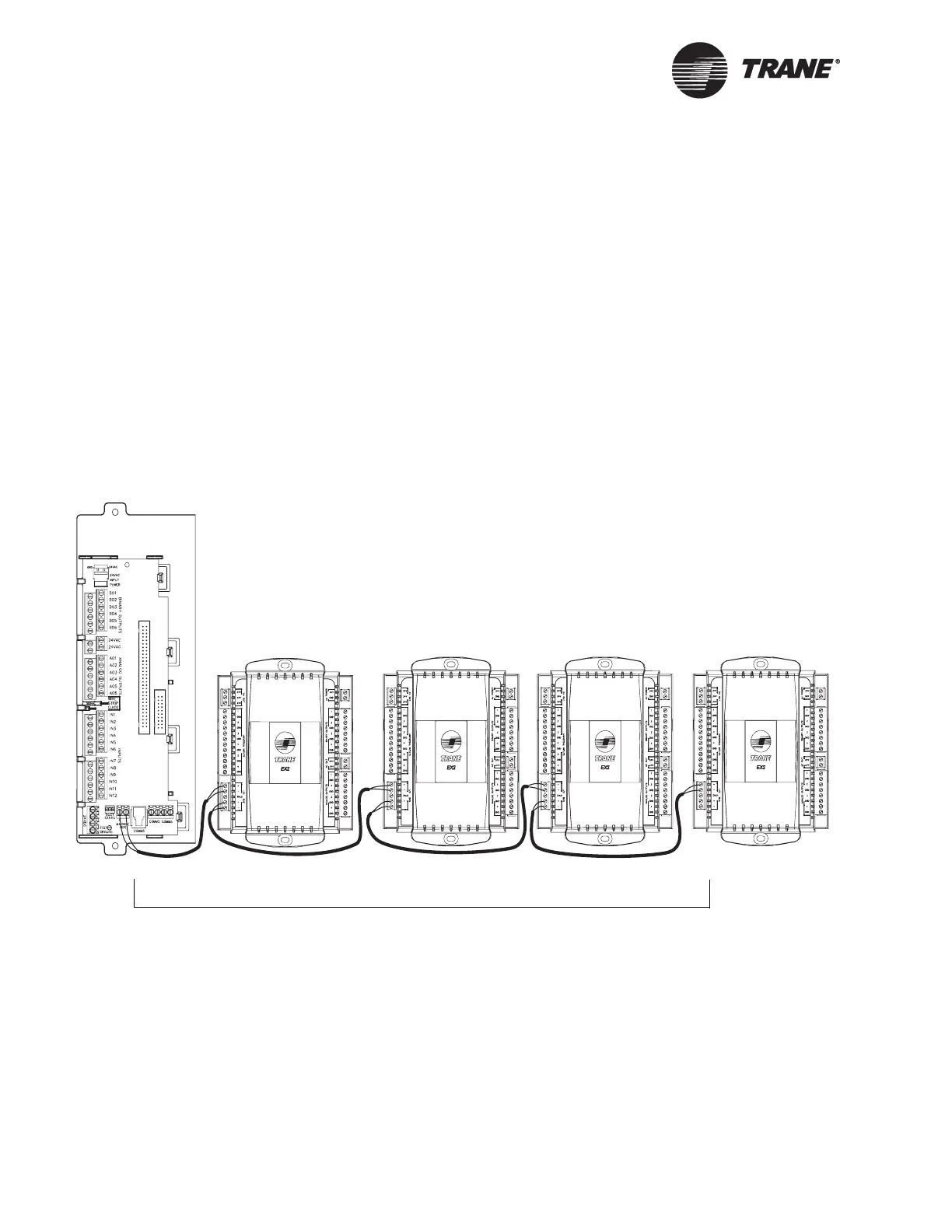
Figure 47. I/O bus wiring example 1
Up to 1000 ft (300 m)
EX2 EX2 EX2 EX2
Tr ace r M P 5 8 1

 Loading...


