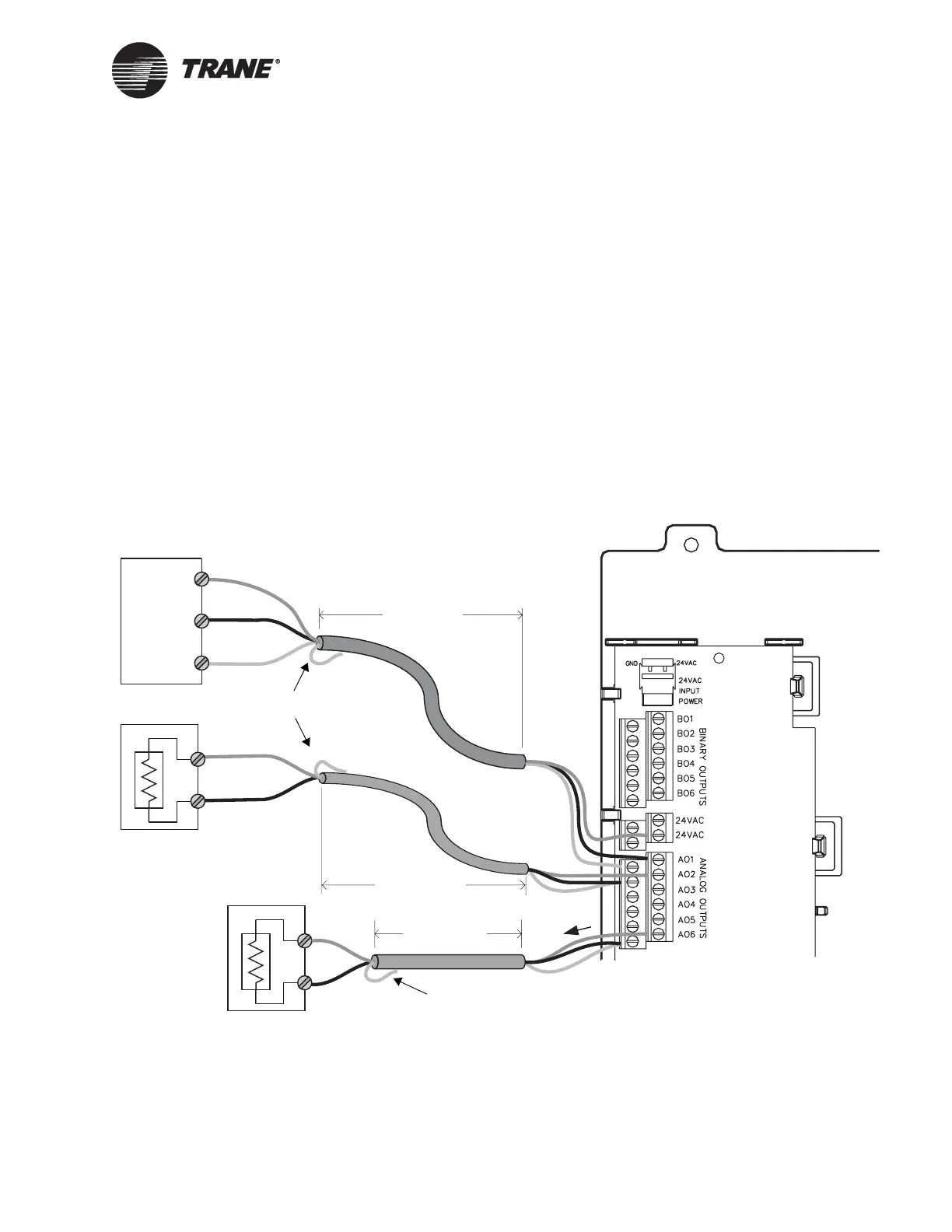
Wiring analog outputs
CNT-SVN01C-EN 25
Wiring analog outputs
The Tracer MP581 controller has six analog outputs. These outputs can
be either 0–10 Vdc outputs or 0–20 mA outputs. Analog outputs control
actuators and secondary controllers.
To wire an analog output:
1. For three-wire applications, use the shield wire as the common con-
nection (see Figure 16). For two-wire applications, connect the shield
wire to a common terminal at the termination board and tape it back
at the output device.
2. Connect the signal wire to an available analog output terminal
(AO1–AO6).
3. Connect the supply wire to a 24 Vac terminal as required.
4. Use the Rover service tool to configure the analog output.
Figure 16. Wiring analog outputs
i
0–10 Vdc output
Load > 500 Ω
< 300 ft
(100 m)
< 1000 ft
(300 m)
0–20 mA output
Load < 500 Ω
Ac powered actuator
Signal
Common
24 Vac
Signal
Common
< 1000 ft
(300 m)
Signal
Common
Tape back shield
Tape back shield

 Loading...


