Setting the I/O bus addresses
CNT-SVN01C-EN 75
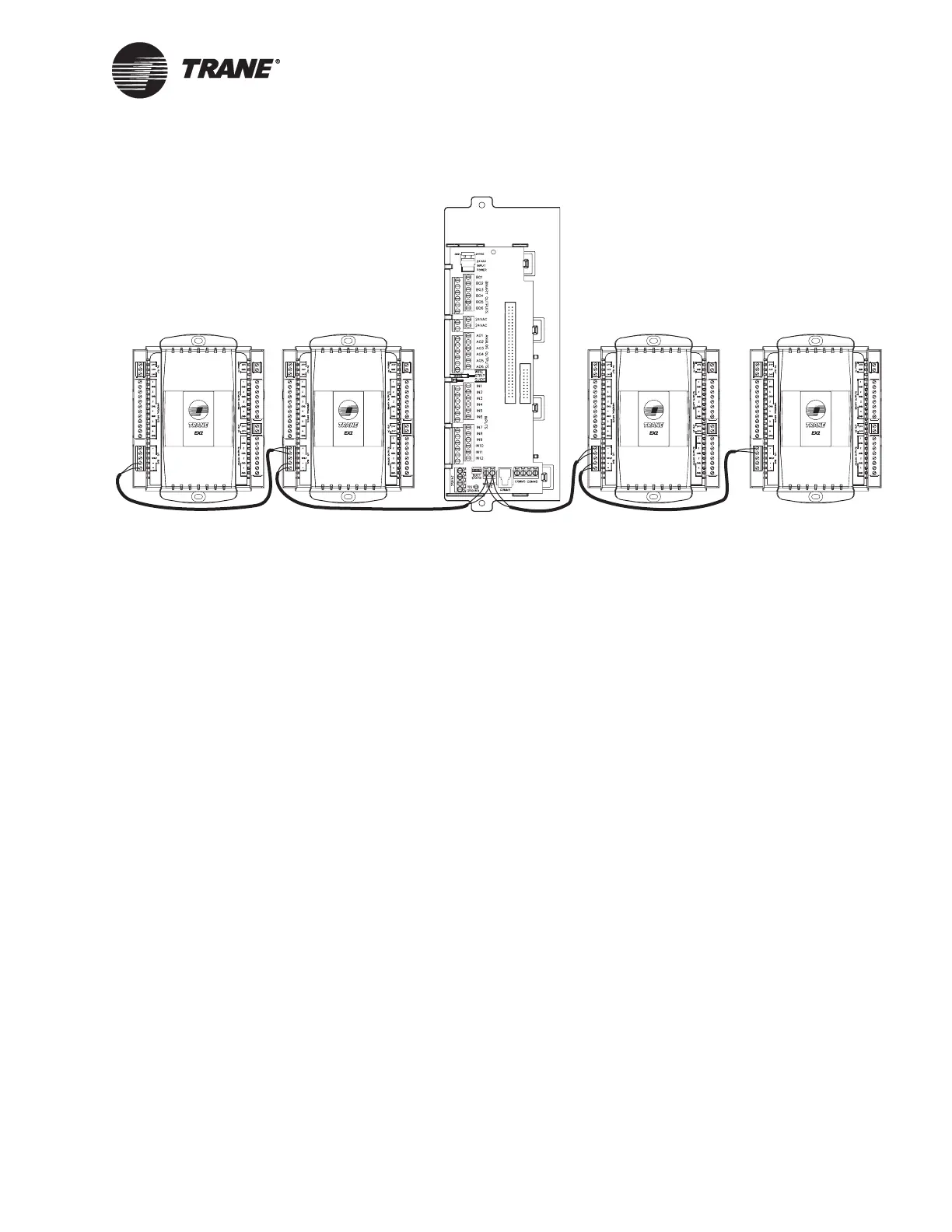
Figure 48. I/O bus wiring example 2
Setting the I/O bus addresses
Each EX2 on the link with the Tracer MP581 must have a unique
address. Configure the address using the DIP switches on the EX2 circuit
board (Figure 49, page 76). The address must match the expansion mod-
ule number as specified on the Unit tab for the MP580/581 in Rover.
Table 10 on page 76 shows the DIP switch settings for expansion modules
1 through 4.

 Loading...


