BAS-SVX62E-EN 17
Wiring Installation
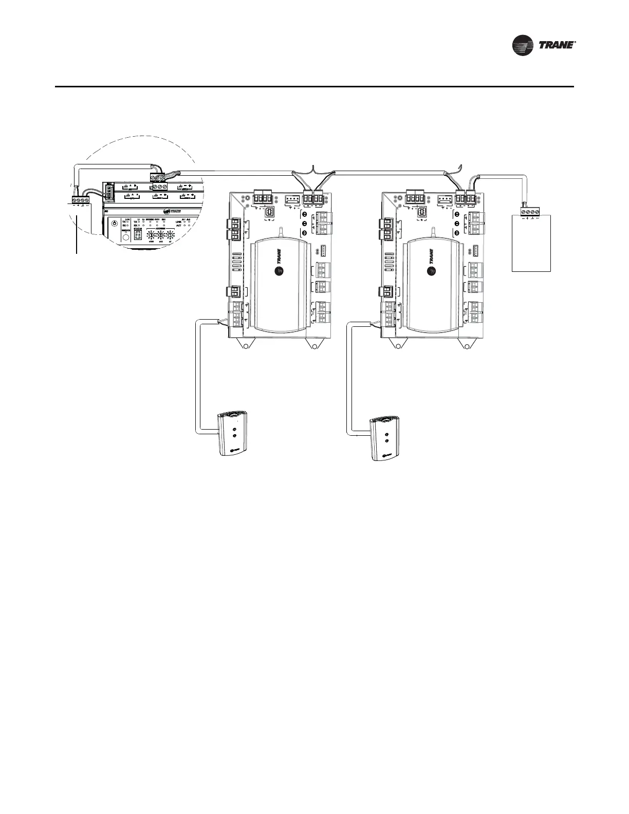
Figure 4. BACnet MS/TP Link Wiring
Wiring Best Practices
To ensure proper network communication, follow the recommended wiring and best practices
below when installing communication wire:
• All wiring must comply with the National Electrical Code™ (NEC) and local codes.
• Ensure that 24 Vac power supplies are consistent in regards to grounding. Avoid sharing 24 Vac
between controllers.
• Avoid over tightening cable ties and other forms of cable wraps. This can damage the wires
inside the cable.
• Do not run communication cable alongside or in the same conduit as 24 Vac power. This
includes the conductors running from TRIAC-type inputs.
• In open plenums, avoid running wire near lighting ballasts, especially those using 277 Vac.
• Use same communication wire type, without terminators, for the zone sensor communication
stubs from the UC210 controller IMC terminals to the zone sensor communication module.
• Zone Sensor communication wiring length limits of 300 ft. (100 m).
Note: For more details, refer to the BACnet Best Practices and Troubleshooting Guide
(BAS-SVX51-EN).
+
+
U
C
210
A
D
D
R
E
S
S
0
1
2
3
4
5
6
7
8
9
x
1
0
1
2
3
4
5
6
7
8
9
x
10
0
1
2
3
4
5
6
7
8
9
x
100
B
O
3
B
O
1
24
VAC
XF
M
R
A
I
1
ZO
N
E
24
VAC
24
VAC
B
O
2
24
V
AC
A
C
TU
A
T
O
R
A
O
2
A
O
1
SER
VI
CE
T
O
O
L
SE
RV
I
C
E
+
24
VDC
IMC
L
INK
R
X
T
X
RX
T
X
+
24
V
DC
I
M
C
UI
2
UI
1
A
I
2
SET
AI
3
DA
T
B
I
1
O
U
T
U
C
210
A
D
D
R
E
S
S
0
1
2
3
4
5
6
7
8
9
x
1
0
1
2
3
4
5
6
7
8
9
x
10
0
1
2
3
4
5
6
7
8
9
x
100
B
O
3
B
O
1
24
VAC
XF
M
R
A
I
1
ZO
N
E
24
VAC
24
VAC
B
O
2
24
V
AC
A
C
TU
A
T
O
R
A
O
2
A
O
1
SER
VI
CE
T
O
O
L
SERVI
C
E
+
24
VDC
IMC
L
INK
R
X
T
X
RX
T
X
+
24
V
DC
I
M
C
UI
2
UI
1
A
I
2
SET
AI
3
DA
T
B
I
1
O
U
T
Tracer SC
UC210
UC210
Zone
Sensor
Zone
Sensor
Trane BACnet
terminator
Trane BACnet
terminator

 Loading...


