BAS-SVX62E-EN 23
Wiring Installation
The wire for the communication stub must be the same that is used for BACnet communication link
wiring. Refer to the section, “Zone Sensor Mounting and Wiring,” p. 22.
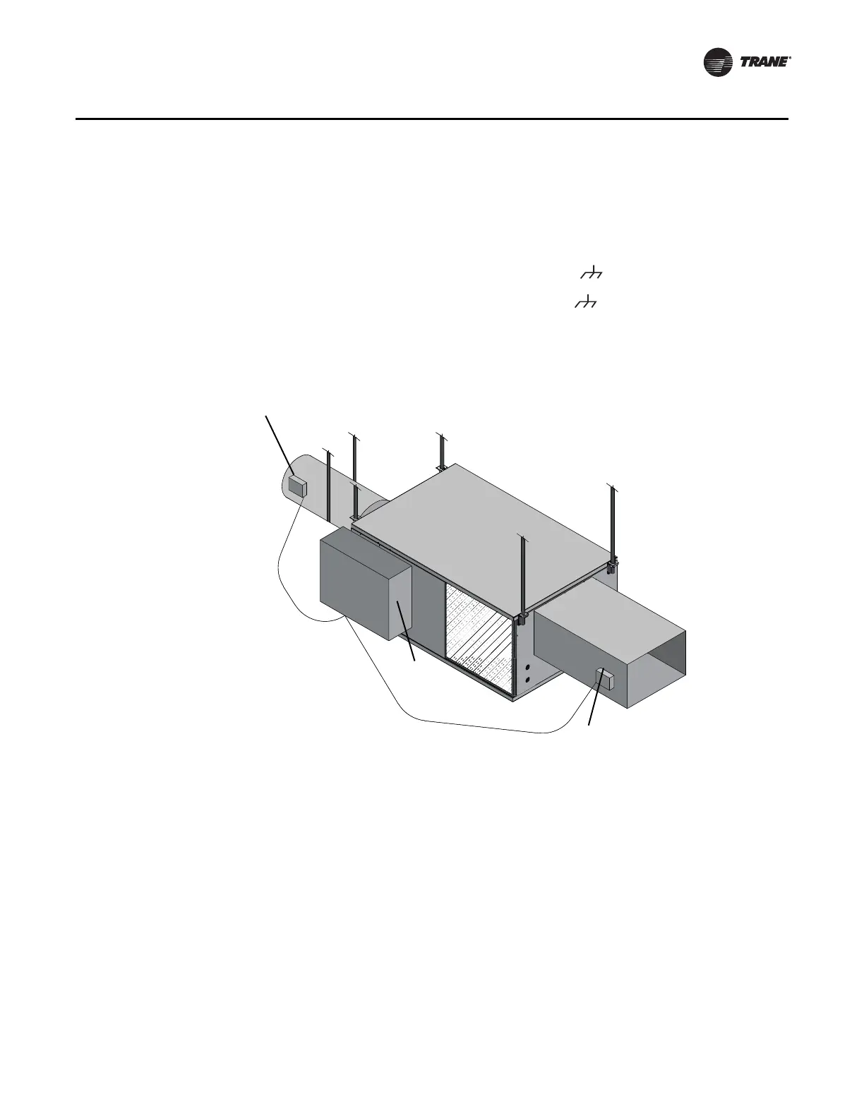
Duct Temperature Sensor Wiring
The UC210 controller has one analog input for a discharge air sensor, which can be user-configured
for supply air temperature. The typical mounting position of the supply air sensor is upstream of
the VAV unit and connected into the UC210 controller at AI3 and (refer to the illustration below).
However, the discharge air temperature sensor may be downstream of the VAV unit (at the
discharge) and connected into the UC210 controller at AI3 and . Refer to the “Appendix: Typical
Trane Factory Wiring Diagrams,” p. 67. For standalone VAV units (those not connected to BACnet
link), an air supply sensor is needed for auto-changeover from cooling to heating mode or from
heating to cooling mode.
Figure 8. Duct sensor locations and wiring
.
Binary Wiring
Binary Input Wiring
Each UC210 controller provides one (1) binary input (BI1), which is configured for occupancy with
the standard VAV code. The binary input can be configured with the Tracer TU service tool for
occupancy or other use. The input associates 0 Vac with open contacts and 24 Vac with closed
contacts. It is activated by a dry contact switch closure. Binary input wiring must meet the following
requirements:
• Use 18 to 22 AWG.
• Maximum wire length 1,000 ft. (300 m).
•Refer to “Appendix: Typical Trane Factory Wiring Diagrams,” p. 67 and to the Wireless Zone
Sensors for Models WTS, WZS, and WDS Installation, Operation and Maintenance Manual
(BAS-SVX04) for zone sensor installation instructions and terminal connections.
Supply air sensor; upstream
Controls
Discharge air sensor; downstream

 Loading...


