20 BAS-SVX62E-EN
Wiring Installation
Wiring Requirements
To ensure proper operation of the UC210 controller, install the power supply circuit in accordance
with the following guidelines:
• The controller must receive AC power from a dedicated power circuit.
Important: Failure to comply may cause the controller to malfunction.
• A dedicated power circuit disconnect switch must be near the controller, easily accessible by
the operator, and marked as the disconnecting device for the controller.
•DO NOT run AC power wires in the same wire bundle with input/output wires.
Important: Failure to comply may cause the controller to malfunction due to electrical noise.
• 18 AWG (0.823 mm
2
) copper wire is recommended for the circuit between the transformer and
the controller.
Connecting the Wires
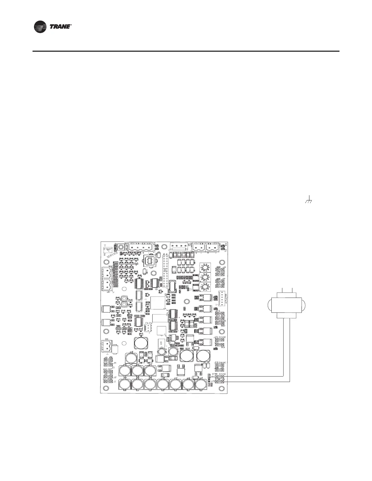
Refer to Figure 7:
1. Disconnect power to the transformer.
2. Connect the 24 Vac secondary wires from the transformer to the XFMR 24 Vac and terminals
on the UC210 controller.
Figure 7. Connecting 24 Vac transformer and ground
24 Vac
transformer
A pigtail connection may be
necessary between earth ground
and/or enclosure ground if the device
is not grounded through one leg of
the transformer wiring.
UC210 Board

 Loading...


