BAS-SVX62E-EN 25
Controller LEDs
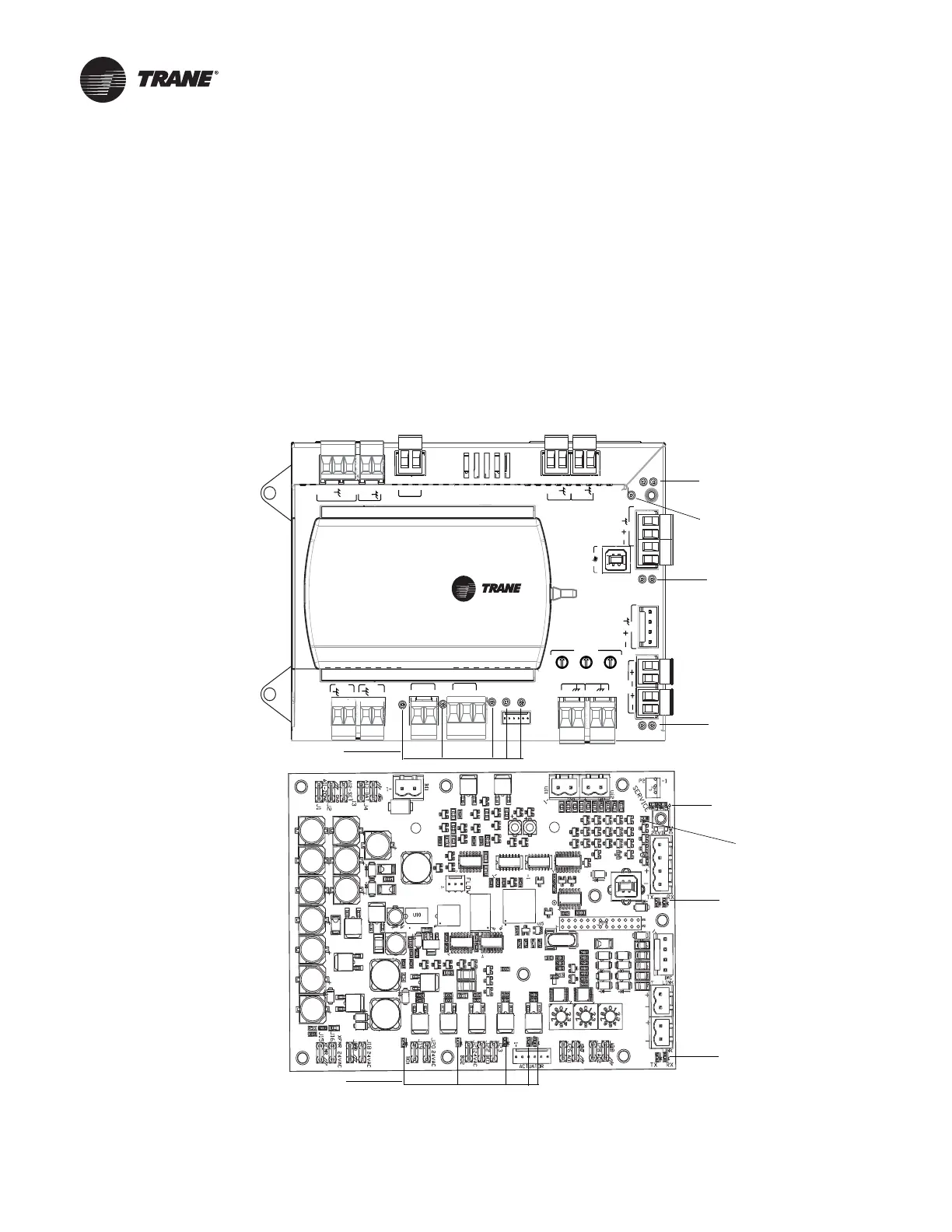
This section describes how to verify and interpret the UC210 controller LEDs and safely operate the
controller. LEDs are used to provide controller serviceability. The UC210 controller has the
following LEDs located on the front (refer to Figure 9 and Table 8, p. 26):
• Marquee LED
• Communication status LEDs and IMC status LEDs
• Service button LED
• Five (5) TRIAC status LEDs
For details about wiring communication links, refer to the BACnet Best Practices and
Troubleshooting Guide (BAS-SVX51-EN).
Figure 9. Controller LEDs
U
C
210
ADDRESS
0
1
2
3
4
5
6
7
8
9
x1
0
1
2
3
4
5
6
7
8
9
x10
0
1
2
3
4
5
6
7
8
9
x100
B
O
3
B
O
1
24
VAC
XFMR
AI1
ZONE
24
VAC
24
VAC
B
O
2
24
VAC
ACTUATOR
A
O
2A
O
1
SERVICE TOOL
SERVI
C
E
+
24
VDC
IMC
LINK
RX
TX
RX
TX
+
24
VDC
IMC
UI
2
UI
1
AI2
SET
AI3
DAT
BI1
OUT
TRIAC status LEDs
Communication
Status LEDs
Marquee LEDs
Service LED
IMC status LEDs
UC210 field
version
UC210 factory
version
TRIAC status LEDs
Communication
Status LEDs
IMC status LEDs
Service LED
Marquee LEDs

 Loading...


