Troubleshooting
CNT-SVX06B-EN 69
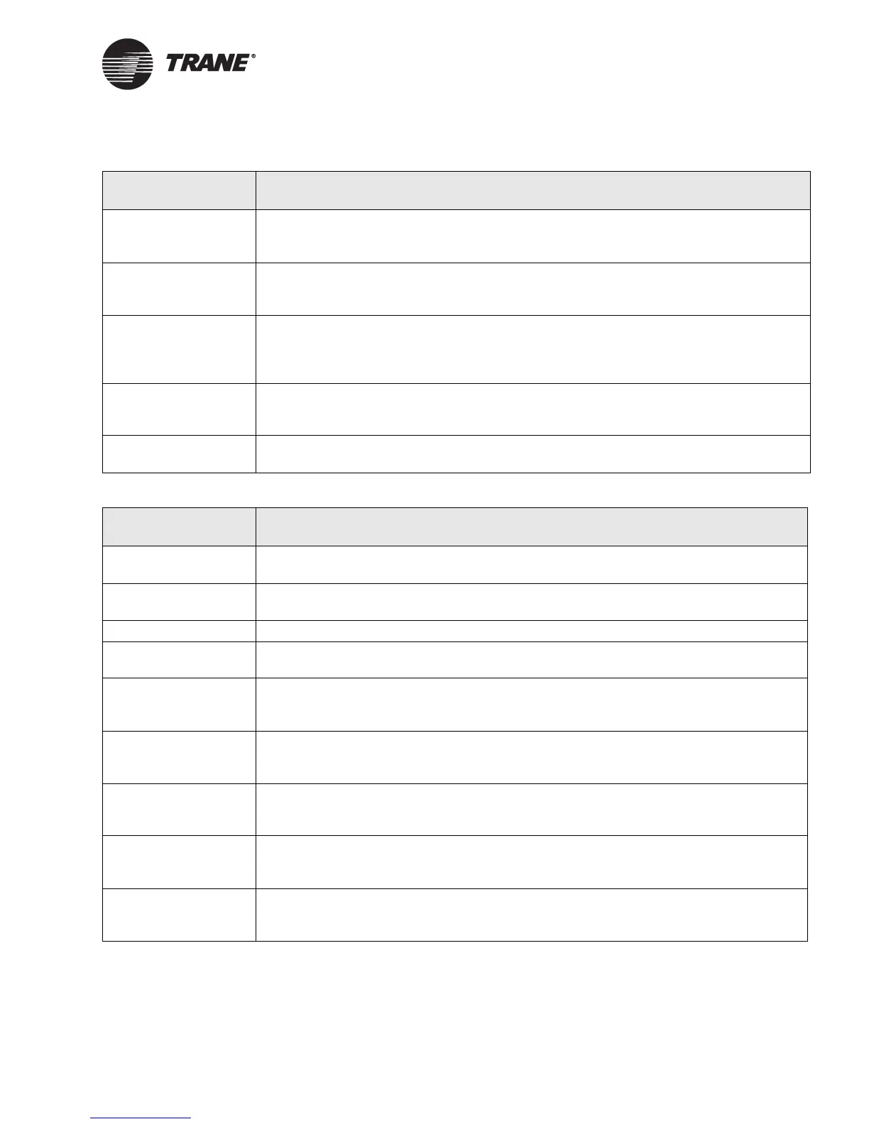
Manual output test The controller includes a manual output test sequence you can use to verify output oper-
ation and associated output wiring. However, based on the current step in the test
sequence, the values may not be open. refer to the “Manual output test” on page 58.
Diagnostic present A specific list of diagnostics affects valve operation, depending whether the unit is config-
ured as 1 heat/1 cool or a water-source heat pump. For more information, see Table 18 on
page 62 and Table 19 on page 64.
Entering water
temperature
sampling logic
The controller includes entering water temperature sampling logic, which is automatically
initiated during 2-pipe and 4-pipe changeover if the entering water temperature is either
too cool or too hot for the desired heating or cooling. (See “AI1: Entering water tempera-
ture sampling” on page 37.)
Unit configuration The controller must be properly configured based on the actual installed end devices and
application (1 heat/1 cool or water-source heat pump). If the unit configuration does not
match the actual end device, the valves may not work correctly.
Valve configuration Make sure the valves are correctly configured, using the Rover service tool, as normally
open or normally closed as dictated by the application.
Table 23. Electric heat does not energize
Probable cause Explanation
Unit wiring The wiring between the controller outputs and the electric heat contacts must be present
and correct for normal electric heat operation. Refer to applicable wiring diagram.
Failed end device Check electric heat element, including any auxiliary safety interlocks, to ensure proper
operation.
Normal operation The controller controls electric heat on and off to meet the unit capacity requirements.
Requested mode off You can communicate a desired operating mode (such as off, heat, and cool) to the con-
troller. If off is communicated to the controller, the unit shuts off all electric heat.
Communicated dis-
able
Numerous communicated requests may disable electric heat, including an auxiliary heat
enable input and the heat/cool mode input. Depending on the state of the communicated
request, the unit may disable electric heat.
Manual output test The controller includes a manual output test sequence you can use to verify output oper-
ation and associated output wiring. However, based on the current step in the test
sequence, the electric heat may not be on. Refer to the “Manual output test” on page 58.
Diagnostic present A specific list of diagnostics affects electric heat operation, depending whether the unit is
configured as 1 heat/1 cool or a water-source heat pump. For more information, see
Table 18 on page 62 and Table 19 on page 64.
Unit
configuration
The controller must be properly configured based on the actual installed end devices and
application (1 heat/1 cool only). If the unit configuration does not match the actual end
device, the electric heat may not work correctly.
No power to the con-
troller
If the controller does not have power, electric heat does not operate. For the ZN511 con-
troller to operate normally, you must apply an input voltage of 24 Vac. If the green LED is
off continuously, the controller does not have sufficient power or has failed.
Table 22. Valves remain open
Probable cause Explanation
 Loading...


