Chapter 9 Troubleshooting
70 CNT-SVX06B-EN
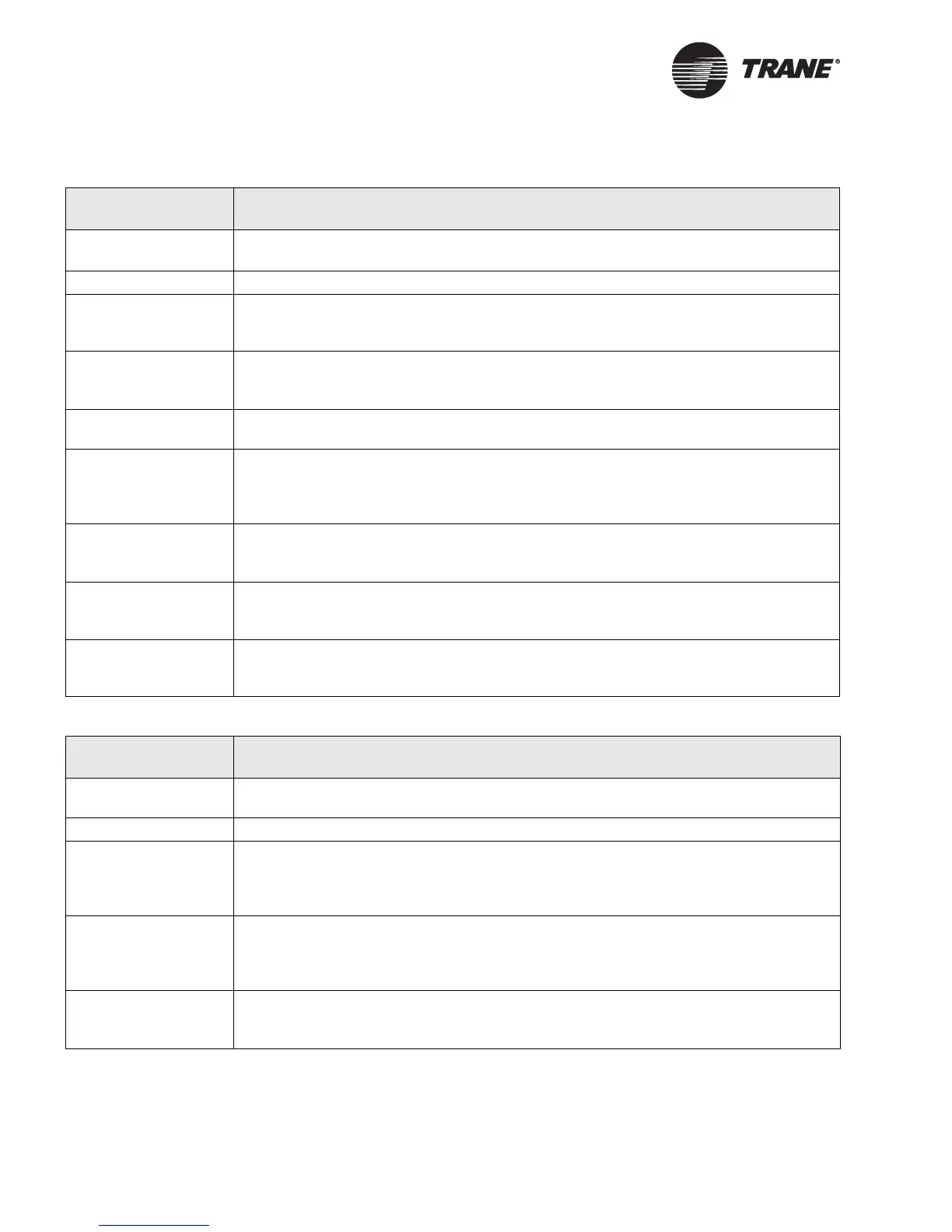
Table 24. Outdoor air damper remains closed
Probable cause Explanation
Unit wiring The wiring between the controller outputs and the outdoor air damper must be present
and correct for normal outdoor air damper operation. Refer to applicable wiring diagram.
Failed end device Check damper actuator to ensure proper operation.
Normal
operation
The controller opens and closes the outdoor air damper based on the controller’s occu-
pancy mode and fan status. Normally, the outdoor air damper is open during occupied
mode when the fan is running and closed during unoccupied mode.
Warm up and cool
down
The controller includes both a morning warm up and cool down sequence to keep the
outdoor air damper closed during the transition from unoccupied to occupied. This is an
attempt to bring the space under control as quickly as possible.
Requested mode off You can communicate a desired operating mode (such as off, heat, or cool) to the control-
ler. If off is communicated to the controller, the unit closes the outdoor air damper.
Manual output test The controller includes a manual output test sequence you can use to verify output oper-
ation and associated output wiring. However, based on the current step in the test
sequence, the outdoor air damper may not be open. Refer to the “Manual output test” on
page 58.
Diagnostic present A specific list of diagnostics affect outdoor air damper operation, depending whether the
unit is configured as 1 heat/1 cool or a water-source heat pump. For more information,
see Table 18 on page 62 and Table 19 on page 64.
Unit configuration The controller must be properly configured based on the actual installed end devices and
application (1 heat/1 cool or water-source heat pump). If the unit configuration does not
match the actual end device, the outdoor air damper may not work correctly.
No power to the
controller
If the controller does not have power, the outdoor air damper does not operate. For the
ZN511 controller to operate normally, you must apply an input voltage of 24 Vac. If the
green LED is off continuously, the controller does not have sufficient power or has failed.
Table 25. Outdoor air damper remains open
Probable cause Explanation
Unit wiring The wiring between the controller outputs and the outdoor air damper must be present
and correct for normal outdoor air damper operation. Refer to applicable wiring diagram.
Failed end device Check damper actuator to ensure proper operation.
Normal
operation
The controller opens and closes the outdoor air damper based on the controller’s occu-
pancy mode and fan status. Normally, the outdoor air damper is open during occupied
mode when the fan is running and closed during unoccupied mode. (See “Outdoor air
damper operation” on page 30 or page 54.
Manual output test The controller includes a manual output test sequence you can use to verify output oper-
ation and associated output wiring. However, based on the current step in the test
sequence, the outdoor air damper may be open. Refer to the “Manual output test” on
page 58.
Unit
configuration
The controller must be properly configured based on the actual installed end devices and
application (1 heat/1 cool or water-source heat pump). If the unit configuration does not
match the actual end device, the outdoor air damper may not work correctly.