Installation
26 RT-SVX21P-EN
Roof Curb
Downflow
The roof curbs for these units consists of a“full perimeter”
enclosure to support the unit just inside of the unit base
rail.The 10 ton high efficiency units contain a support base
alignment rail and will extend past the end of the roof curb
as shown in figures below.
Before installing any roof curb, verify;
• It is the correct curb for the unit,
• It includes the necessary gaskets and hardware,
• The installation location provides the required
clearance for proper operation,
• The curb is level and square.The top surface of the
curb must be true to assure an adequate curb-to-unit
seal.
Verify that appropriate materials were used in the
construction of roof and ductwork. Combustible materials
should not be used in the construction of ductwork or roof
curb that is in close proximity to heater elements or any
hot surface. Any combustible material on the inside of the
unit base should be removed and replaced with
appropriate material.
Step-by-step curb assembly and installation instructions
ship with each accessory roof curb kit. Follow the
instructions carefully to assure proper fit-up when the unit
is set into place.
Note: To assure proper condensate flow during
operation, as well as proper operation of the
condensate overflow switch (if equipped), the unit
and curb must be level.
If the unit is elevated, a field constructed catwalk around
the unit is strongly recommended to provide easy access
for unit maintenance and service.
Recommendations for installing the Supply Air and Return
Air ductwork joining the roof curb are included in the curb
instruction booklet. Curb ductwork must be fabricated and
installed by the installing contractor before the unit is set
into place.
Note: For sound consideration, cut only the holes in the
roof deck for the ductwork penetrations. Do not cut
out the entire roof deck within the curb perimeter.
If a Curb Accessory Kit is not used:
• The ductwork can be attached directly to the factory-
provided flanges around the unit’s supply and return
air openings. Be sure to use flexible duct connections
at the unit.
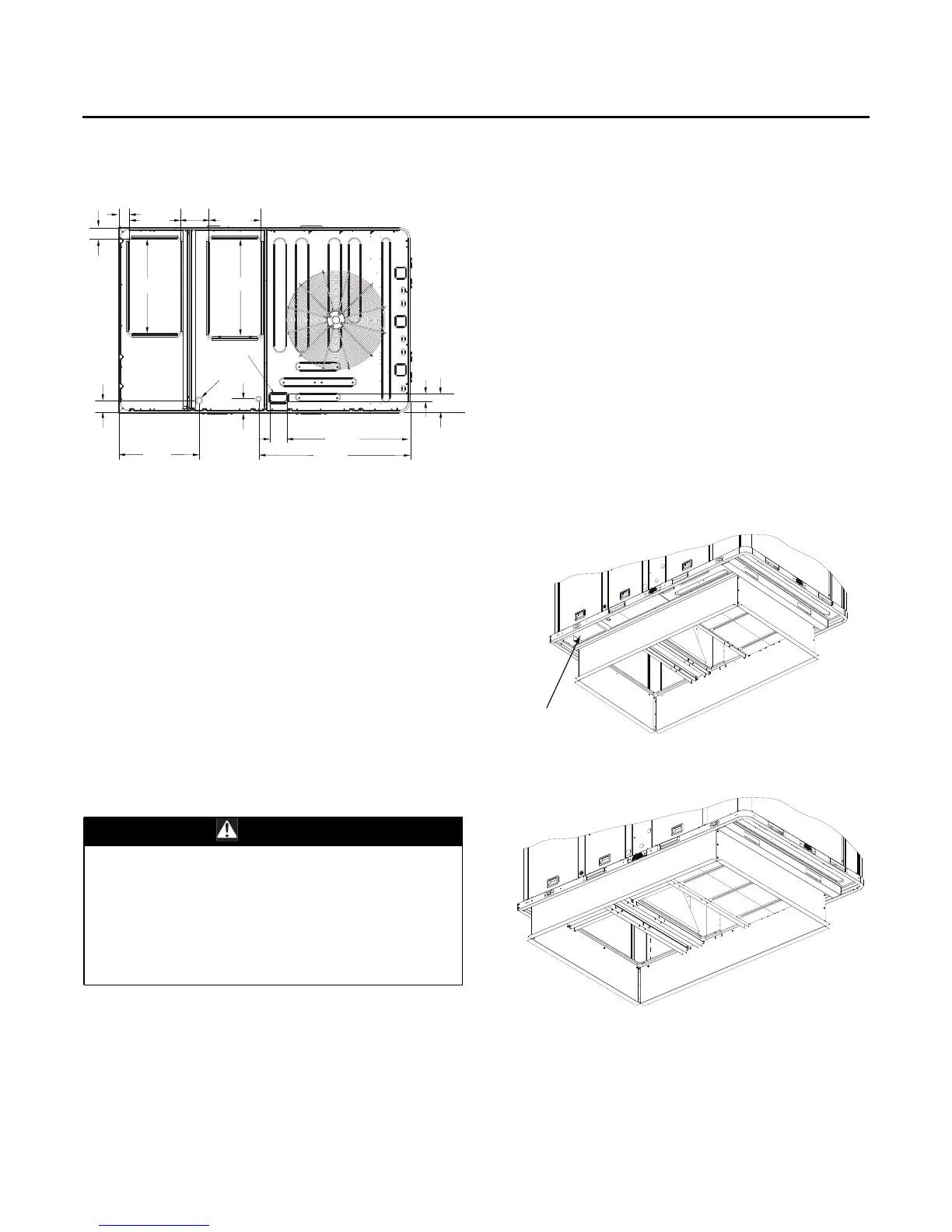
Figure 21. 10 ton high efficiency unit - downflow supply
& return air openings w/ through-the-base
utilities
WARNING
Combustible Materials!
Maintain proper clearance between the unit heat
exchanger, vent surfaces and combustible materials.
Refer to unit nameplate and installation instructions for
proper clearances. Improper clearances could result in
combustible materials catching on fire. Failure to
maintain proper clearances could result in death or
serious injury or property damage.
Supply
Return
32 1/8”
816 MM
33”
MM
4”
102 MM
17 1/2”
444 MM
17 1/2”
444 MM
3 5/8”
92 MM
9 7/8”
251 MM
4 1/8”
104 MM
27 5/8”
701 MM
THROUGH THE
BASE CONDENSATE
4 5/8”
119 MM
THROUGH THE
BASE ELECTRICAL
51 13/16”
1316 MM
42 3/16”
1072 MM
5 7/8”
149 MM
6 3/8”
163 MM
2 3/4”
71 MM
Figure 22. View for base to roof curb alignment
YHC120E on 50" x 84" roof curb
Figure 23. View for base to roof curb alignment
YHC120E on 60" x 84" roof curb
Base Alignment Bracket