Installation
RT-SVX21P-EN 31
TCO1 Instructions
If the unit being installed is listed in the following list, the
limit controlTCO1 must be replaced with the extra limit
control shipped in the heater compartment. ReplaceTCO1
following the instructions in steps 1 through 3 below. If the
unit being installed does not correspond to any in the
following list, skip steps1 through 3 and go on to next step
in the installation process.
Unit Model Number
YSC072F**(H,Z),YSC092F**(M,Y),YSC092F**(H,Z),
YSC102F**(M,Y),YSC102F**(H,Z),YSC120F**(L,X),
YSC120F**(H,Z),YSC090F**(L,X),YHC092F(M,Y),
YHC102F**(M,Y),YHC120E**(L,X),YHC120E**(H,Z).
1. Remove the heat section access panel.
2. RemoveTCO1 from shipping location, attached to the
combustion blower.
3. Replace and discard the existingTCO1 originally
installed at the factory for down flow operation with
theTCO1 shipped attached to the combustion blower
for horizontal operation.
4. Replace heat section access panel.
Return Air Smoke Detector
The factory installed Return Air Smoke Detector is
installed in the downflow discharge position. No
additional field setup is required.
If a unit is to be converted to horizontal discharge, the
following conversion must be performed:
1. If the unit has an economizer, it must be pulled out in
the operating position.
2. Remove the 3 screws from the mounting brackets.
Refer to downflow view for screws locations.
3. Lift the tube and bracket from the downflow duct
opening. Rotate the tube and bracket assembly 180
degrees ensuring that the holes on the copper sensing
tube face away from the unit and face the return air
ductwork. Refer Figure 34, p. 32 and Figure 35, p. 32
for screws location.
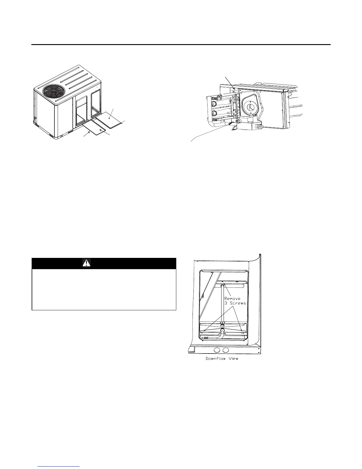
Figure 31. Supply and return covers
WARNING
Hazardous Voltage!
Disconnect all electric power, including remote
disconnects before servicing. Follow proper lockout/
tagout procedures to ensure the power can not be
inadvertently energized. Failure to disconnect power
before servicing could result in death or serious injury.
Insulation side
down
Supply duct cover
Insulation side up
Return duct
cover
Figure 32. TCO1 location (YHC120E)
Figure 33. Downflow view
CO1 limit is located above
the burner on the YHC120E models
Replace original factory installed TCO1
with optional TCO1 attached to blower
housing for field convertion to horizontal discharge