Installation
28 RT-SVX21P-EN
• Verify correct model, options and voltage from unit
nameplate.
• Verify that the installation location of the unit will
provide the required clearance for proper operation.
• Assemble and install the roof curb (if applicable). Refer
to the latest edition of the curb installers guide that
ships with each curb kit.
• Fabricate and install ductwork; secure ductwork to
curb.
• Install pitch pocket for power supply through building
roof. (If applicable)
• Rigging the unit.
• Set the unit onto the curb; check for levelness.
• Ensure unit-to-curb seal is tight and without buckles or
cracks.
• Install and connect a condensate drain line to the
evaporator drain connection.
Note: Condensate Overflow Switch (if equipped) will not
work if unit is not leveled properly.
Factory Installed Economizer
• Ensure the economizer has been pulled out into the
operating position. Refer to the economizer
installation guide for proper position and setup.
• Install all access panels.
Temperature Limit Switch Usage for Gas
Heat Units
Units are factory shipped in the down flow discharge
configuration but can be field converted to a horizontal
discharge configuration. Some, but not all units require a
differentTCO1 limit switch, which is attached to the
combustion blower motor if horizontal discharge
configuration is used.
Note: The following units require a limit switch change
out for horizontal discharge.The additional limit
switch is shipped attached to the combustion
blower housing:YSC036E**(M,Y),
YSC036E**(H,Z),YSC048E**(H,Z),
YSC048E**(M,Y) belt drive ID motor,
YSC060E**(H,Z) direct drive ID motor,
YHC047E**(L,X),YHC048E/F**(L,X) direct drive ID
motor,YHC060E/F**(L,X) belt drive ID,
YHC036E**(M,Y),YHC037E**(M,Y),YHC048E/
F**(M,Y),YHC060E/F**(M,Y) direct drive ID motor,
YHC036E**(H,Z),YHC048E/F**(H,Z) belt drive ID
motor,YHC060E/F**(H,Z),YSC072F**(H,Z),
YSC090F**(L,X),YSC092F**(H,Z),
YSC102F**(H,Z),YSC120F**(L,X),
YSC120F**(H,Z),YHC092F**(M,Y),
YHC102F**(M,Y),YHC120E**(H,Z).
If any of the aforementioned units are installed in the down
flow discharge configuration, remove the additionalTCO1
limit switch from the combustion blower motor and
discard.
BD= Belt drive ID motor
DD= Direct drive ID motor
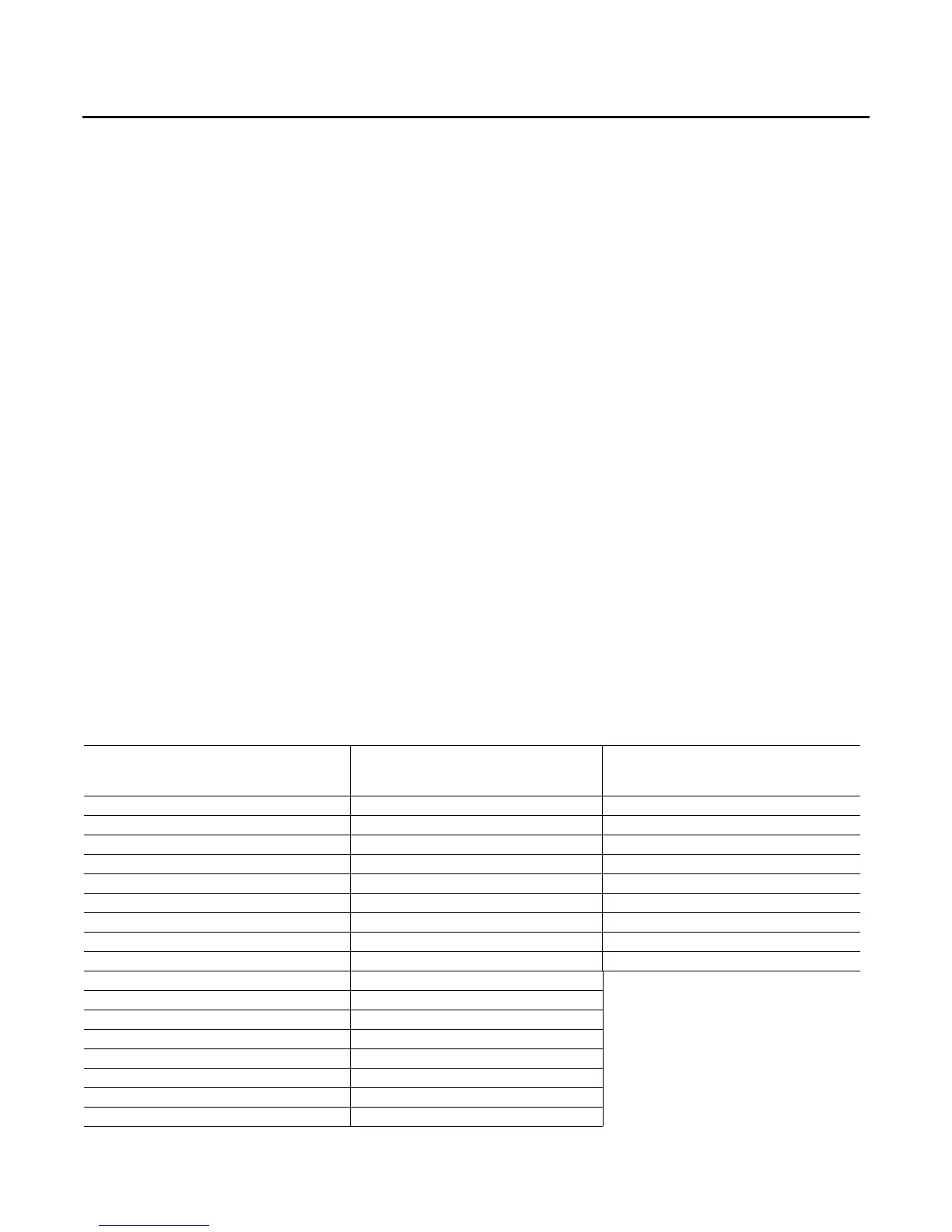
Table 3. TC01 tripping values
Unit Model (Std.
Eff.)
TCO1 Tripping
Values - Downflow/
Horizontal
Unit Model - (High
Eff. - 15 SEER)
TCO1 Tripping
Values -Downflow/
Horizontal
Unit Model
(High Eff. - 17 Plus)
TCO1 Tripping
Values -Downflow/
Horizontal
YSC036E**(L,X)-DD 180F YHC036E**(L,X)-DD 180F YHC037**(L,X) 190F
YSC036E**(L,X)-BD 170F YHC036E**(L,X)-BD 170F YHC037**(M,Y) 170F / 220F
YSC036E**(M,Y)-DD 170F / 190F YHC036E**(M,Y)-DD 170F / 190F YHC037**(H,Z) 220F
YSC036E**(M,Y)-BD 180F / 190F YHC036E**(M,Y)-BD 180F / 190F YHC047**(L,X) 145F / 155F
YSC036E**(H,Z)-DD 170F / 190F YHC036E**(H,Z)-DD 170F / 190F YHC047**(M,Y) 170F
YSC036E**(H,Z)-BD 155F / 190F YHC036E**(H,Z)-BD 155F / 190F YHC047**(H,Z) 220F
YSC048E**(L,X)-DD 180F YHC048E/F**(L,X)-DD 145F / 155F YHC067**(L,X) 140F
YSC048E**(L,X)-BD 170F YHC048E/F**(L,X)-BD 155F YHC067**(M,Y) 170F
YSC048E**(H,Z)-DD 155F / 210F YHC048E/F**(M,Y)-DD 150F / 170F YHC067**(H,Z) 170F
YSC048E**(M,Y)-BD 170F / 190F YHC048E/F**(M,Y)-BD 170F / 180F
YSC048E**(M,Y)-DD 180F YHC048E/F**(H,Z)-DD 220F
YSC048E**(H,Z)-BD 155F / 200F YHC048E/F**(H,Z)-BD 220F / 260F
YSC060E**(L, X) 170 YHC060E/F**(L,X)-DD 140F
YSC060E**(M,Y) 170F YHC060E/F**(L,X)-BD 155F / 145F
YSC060E**(H,Z)-DD 170F / 200F YHC060E/F**(M,Y)-DD 145F / 170F
YSC060E**(H,Z)-BD 170F YHC060E/F**(M,Y)-BD 170F
YSC072F**(M,Y) 155F YHC060E/F**(H,Z)-DD 190F / 220F
continued on next page