Installation
RT-SVX21P-EN 37
Note: Resistance in excess of 2.5 ohms per conductor can
cause deviations in the accuracy of the controls.
Note: Ensure that the wiring between controls and the
unit’s termination point does not exceed two and a
half (2.5) ohms/conductor for the length of the run.
• Do not run the electrical wires transporting DC signals
in or around conduit housing high voltage wires.
• Route low voltage wiring per illustrations on page 38.
DC Conductors
Table 6. Zone sensor module wiring
Distance from Unit to Control Recommended Wire Size
0 - 150 feet 22 gauge
0 - 45.7 m .33 mm2
151 - 240 feet 20 gauge
46 - 73.1 m .50 mm2
241 -385 feet 18 gauge
73.5 - 117.3 m .75 mm2
386 - 610 feet 16 gauge
117.7 - 185.9 m 1.3 mm2
611 - 970 feet 14 gauge
186.2 - 295.7 m 2.0 mm2
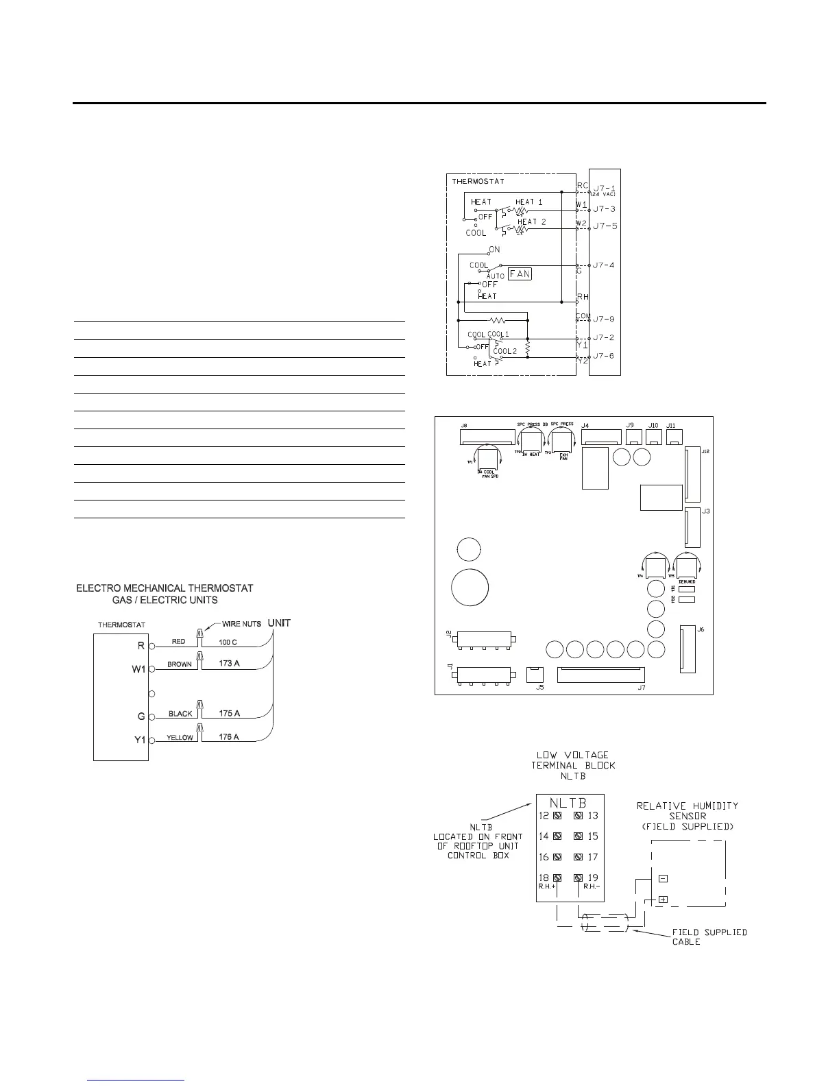
Figure 40. Typical field wiring diagrams for
electromechanical
Figure 41. ReliaTel™ conventional thermostat field
wiring diagrams
Figure 42. ReliaTel™ options module
Figure 43. ReliaTel™ relative humidity sensor
(dehumidification option)
RTRM