0221
23
3. INSTALLATION
3. INSTALLAZIONE
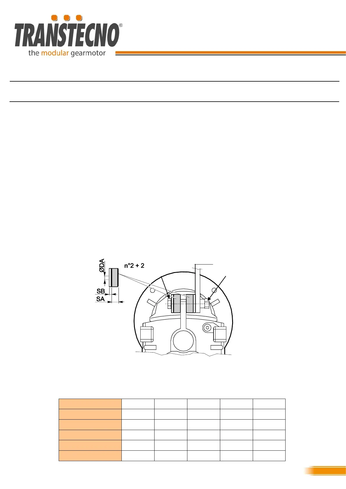
3.12 Torque arm assembly
3.12 Montaggio dei bracci di reazione
Per il montaggio con braccio di reazione dei riduttori pendo-
lari ATS e ITS fare riferimento a questa descrizione.
Utilizzare il kit braccio di reazione messo a disposizione da
Transtecno.
● SB indica lo spessore delle rondelle rigide comprese nel kit
● SA indica lo spessore delle rondelle ammortizzanti compre-
sa nel kit
● øDA indica il foro passante delle due rondelle
● M indica la tipologia di viti e dadi da utilizzare
● ∆L indica la distanza tra la rondella rigida ed il fissaggio
macchina
Inserire le rondelle del kit come mostrato in figura.
Utilizzare solo le tipologie di viti e dadi segnalati a tabella per
ciascuna taglia di riduttore.
Rispettare la distanza ∆L per evitare di serrare assialmente il
braccio di reazione.
ATS; ITS;
SA SB øDA M ∆L
ATS902/3 5 15 13 M12 1,5
ATS912/3 5 15 13 M12 1,5
ITS922/3 5 15 13 M12 1,5
ITS932/3 10 30 21 M20 1,5
ITS942/3 10 30 21 M20 1,5
To fit the torque arms of the ATS and ITS shaft-mounted
gearmotors refer to the following description:
Use the torque arm kit provided by Transtecno.
● SB indicates the thickness of the rigid washers in the kit
● SA indicates the thickness of the shock-absorbing washers
in the kit
● øDA indicates the through-hole of both washers
● M indicates the type of screws and nuts to be used
● ∆L indicates the distance between the rigid washer and the
machine fixing point
Fit the kit washers as shown in the Figure.
Use only the types of screws and nuts indicated in the table
for each size of gearmotor.
Observe the distance ∆L to avoid axially tightening the torque
arm.
∆L
M M