0221
24
3. INSTALLATION
3. INSTALLAZIONE
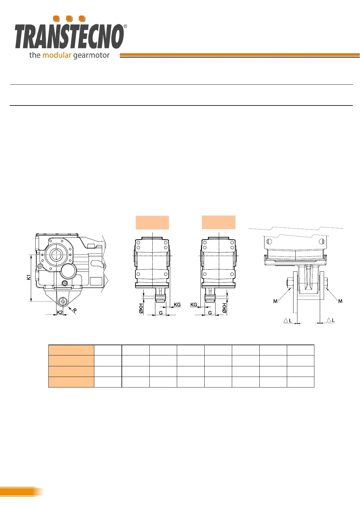
3.12 Torque arm assembly
3.12 Montaggio dei bracci di reazione
Per il montaggio con braccio di reazione dei riduttori ortogo-
nali ITB fare riferimento a questa descrizione.
Utilizzare il kit braccio di reazione messo a disposizione da
Transtecno.
Fissare assialmente l’albero di uscita al cavo di uscita del
riduttore come mostrato nei paragrafi precedenti.
Supportare la boccola del braccio di reazione da entrambi I
lati.
Utilizzare solo le tipologie di viti e dadi segnalati a tabella per
ciascuna taglia di riduttore.
Rispettare la distanza ∆L per evitare di serrare assialmente il
braccio di reazione.
ITB
K1 K2 KG KH G R M ∆L
ITB423 200 30 25 16.5 60 29 M16 1,5
ITB433 250 35 25 16.5 60 29 M16 1,5
ITB443 300 35 30 25 80 40 M24 1,5
To fit the torque arms of ITB bevel helical gearmotors, refer
to the following description:
Use the torque arm kit provided by Transtecno.
Axially secure the output shaft in the output bore of the gear-
motor, as described in the previous paragraphs.
Support the torque arm bush on both sides.
Use only the types of screws and nuts indicated in the table
for each size of gearmotor.
Observe the distance ∆L to avoid axially tightening the torque
arm.
BRDX
BRSX