0221
25
3. INSTALLATION
3. INSTALLAZIONE
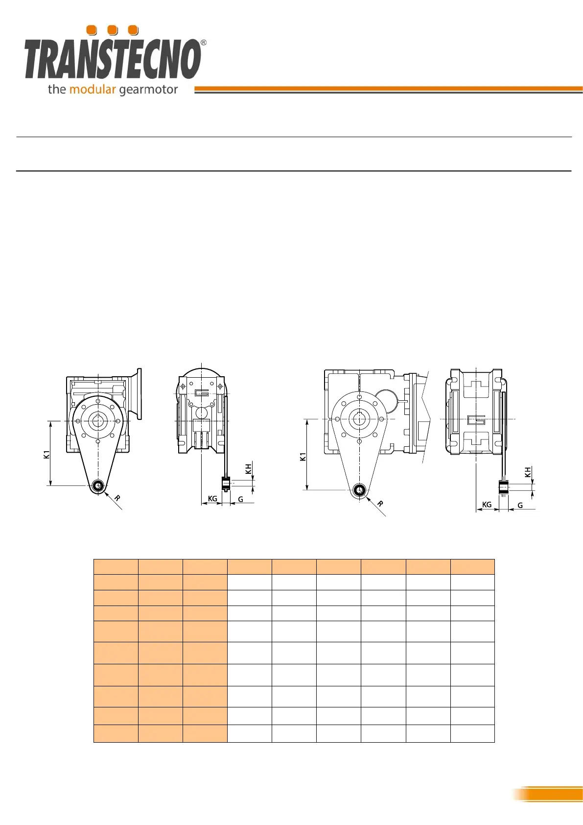
3.12 Torque arm assembly
3.12 Montaggio dei bracci di reazione
Per il montaggio con braccio di reazione dei riduttori ortogo-
nali CMB e dei riduttori a vite senza fine CM, CMP, CMM,
CMPU e CL fare riferimento a questa descrizione.
Utilizzare il kit braccio di reazione messo a disposizione da
Transtecno.
Fissare assialmente l’albero di uscita al cavo di uscita del
riduttore come mostrato nei paragrafi precedenti.
Supportare la boccola del braccio di reazione da un solo lato
oppure da entrambi i lati senza fissarla assialmente.
Inserire le viti ( o spine ) della misura indicate nella Colonna
M della tabella a seconda della grandezza riduttore
CMB; CM; CMP; CMM; CMPU; CL; CLP; CLL; CLPU;
M R KG KH K1 G CMB CM CL
M8 15 23 8 85 14 030 030
M10 18 31 10 100 14 402 040 040
M10 18 38 10 100 14 502 050 050
M10 18 47.5 10 150 14 633 063
M20 30 46.5 20 200 25 070 070
M20 30 46.5 20 200 25 075
M20 30 56.5 20 200 25 903 090
M24 35 62 25 250 30 110
M24 35 69 25 250 30 130
To fit the torque arms of CMB orthogonal gearmotors and
CM, CMP, CMM, CMPU and CL worm gearmotors, refer to
the following description:
Use the torque arm kit provided by Transtecno.
Axially secure the output shaft in the output bore of the gear-
motor, as described in the preceding paragraphs.
Support the torque arm bush on one side only or on both
sides without axially securing it.
Insert the screws (or pins) of the size indicated in Column M
of the table, depending on the size of the gearmotor.