UVM-1000
LIT-12013155
6
Overview of Operation
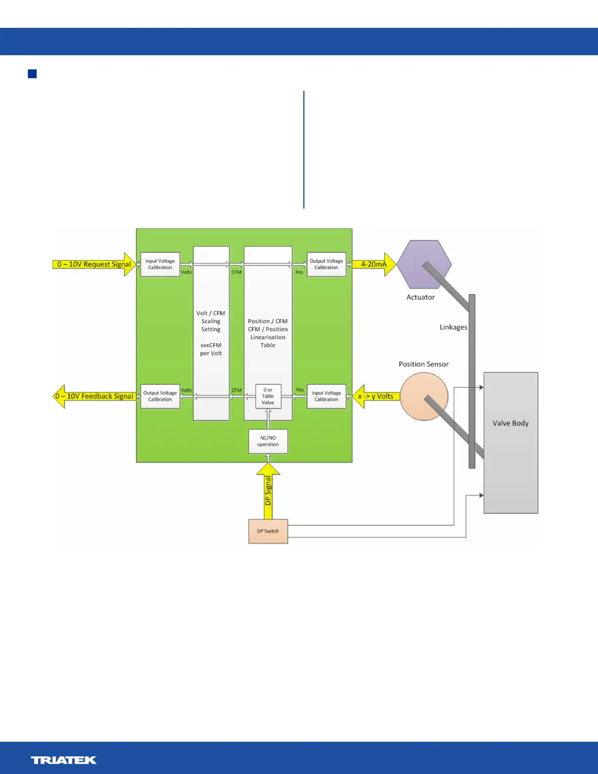
Figure 2. UVM Use with DP Switch
Digital Input DP Switch
The UVM has the ability to accept a digital input DP switch. The
pneumatics of the DP switch are connected across the valve, and
the factory supplied switch is set to trip at 0.6 in. W.G.
Any pressure across the valve below this is to be interpreted as
the valve cfm is inaccurate or non-existent. The DP switch signal,
when enabled in the UVM, is used to provide a 0 cfm feedback
signal should the pressure across the valve drop below the 0.6
in. W.G. threshold.
The DP switch functionality can also be implemented by using
a pressure sensor with a 0-5 V output. The UVM can accept the
0-5 V signal and, via user gain and oset settings, convert it to an
internal pressure value.
Typically a 0-4 or 5 in. W.G. sensor would be used. When
enabled in the UVM, this value can be compared to a minimum
pressure value (typically 0.6 in. W.G.) as a threshold below
which, as like the DP switch, the cfm feedback signal goes to 0.
 Loading...