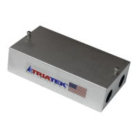
UVM-1000
LIT-12013155
17
This guide is specic to the installation of the FMS-1655 Room
Pressure Controller with the UVM. The information provided is
merely suggestive and does not supersede any data provided in
the Triatek Programming and Installation Guides.
1. The controller must be opened by rst loosening the four
screws in the sides. Then separate the FMS Controller from
the back plane.
2. Check Dip Switches in the FMS Controller.
Note: S1 has 8 switches. Switches 1 through 4 are to congure
Analog Inputs 1 through 4 as either voltage or current Input while
switches 5 through 8 set the signal range of Analog Inputs 1 to 4
as 0-5 VDC or 4-20 mA when selected OFF or 0-10 VDC when
selected ON. In other words, switch 5 sets the range for analog
input 1. Likewise, switch 6 sets the range for analog input 2. For
example, setting switch 1 ON and 5 OFF sets Analog Input_1
as signal type Current (mA) with a range of 4-20 mA. However,
setting switch 3 OFF and 7 ON sets Analog Input_3 as signal type
Voltage (V) with a range of 0-10 VDC.
3. Switch 1 of S1 should be ON for Current (mA) signal input
when using Triatek Digital sensors due to the Dierential
Pressure output type being 4-20 mA.
4. Please consider the additional devices such as UVM
feedback signals for type and range on designated inputs. For
Example: Supply UVM (Vo to Ground) feedback should be on
Analog Input 3. The input must be set as Voltage by setting
S1 switch 3 OFF with a 0-10 VDC range with switch 7 ON. If
the FMS is expected to control for volumetric oset, then the
Exhaust MUST be controlled by Analog Output 4 (0-10 VDC).
Therefore, the feedback of the Exhaust should be on Analog
Input 4. The input must be set as Voltage and 0-10 VDC by
setting S1 switch 4 OFF and switch 8 ON.
5. Analog Output should be set to determine the voltage range
preferred for the UVM Input signal. The UVM is designed
for a 0-10 VDC control Input signal. Therefore, dip switch
S4 should be set for 0-10 VDC for outputs controlling UVM
devices. Set all S4 switches to OFF for 0-10 VDC outputs of
analog outputs 1-4.
6. Next is the Protocol switch. S3 switch 5 should be OFF while
all other switches are ON for BACnet protocol and no network
termination required of FMS165X controller.
7. At this point, the FMS controller hardware settings have
been completed. However, the software congurations must
be completed for proper operation of controller. Also, the
wiring of the controller must be veried for correct device
terminations of inputs and outputs.
Wiring
Power
The FMS Controller is powered by (fused) 24 VAC.
IMPORTANT: Do not power both FMS Controller and valve
actuator with the same Triatek issued isolation transformer.
Analog Inputs
Most Common Conguration with Triatek devices for volumetric
oset control.
Analog Input 1 (AI_1): 3 Wire mA output sensor is wired to AI1.
Three wires are Sensor Power (DIGITAL SNS_PWR), Ground
(GND) and ANALOG_INput 1 (AI_1). The sensor should be wired
as follows from Controller to Sensor: DIGITAL SNS_PWR to +Vin;
GND to GND; AI_1 to Io.
GND and Io. Io is the 4-20 mA output to controller termination.
Note: A third party sensor can be used. However, the sensor
range must be entered correctly. Be sure to convert the sensor
pressure range from Pa to in. W.C. as the scale is in. W.C. by
default.
Analog Input 2 (AI_2): Temperature Sensor should be wired here
AI_2 to GRND.
Analog Input 3 (AI_3): 2 Wires from Supply UVM VO and ground
for a 0-10 VDC feedback signal to the FMS165x Analog Input_3
and ground. This connection is important for the display of Airow
Value on AI_3 for Supply.
Analog Input 4 (AI_4): 2 Wires from the Exhaust UVM VO and
ground for a 0-10 VDC feedback signal to the FMS165x Analog
Input_4 and ground. This connection is important for the display of
Airow Value on AI_4 for Exhaust.
Note: If volumetric oset control is preferred, then Analog Input_3
must be congured rst for Flow. Then congure Analog Input_4
for ow and the volumetric oset option will be made available.
The volumetric oset option is only made available in the menu of
analog input 4 if analog input 3 has been congured for ow.
Analog Outputs
The output wiring (control signal) goes from FMS back plane CN3
Analog Outputs 1-4 to UVM IN and Ground. Be sure to map the
correct input to output for expected control. I recommend mapping
analog output 4 to analog input 4. Also, analog output 3 should be
mapped to analog input 3. This mapping is accomplished in the
Main Menu >> System Setup >> Next >> Ai/Ao Mapping.
Analog Output 4: 2 Wires to the UVM Control Board IN and
Ground of valve being controlled to track for volumetric oset
control. Typical with BMS controlling Supply or Exhaust and the
FMS is expected to regulate Supply or Exhaust by tracking for
volumetric oset control.
Auxiliary Outputs
The auxiliary outputs are provided for the following voltages:
• 5 VDC
• 10 VDC
• +V = 32 VDC Typically used to power Occupancy Sensor
Network
BMS wiring goes on connector CN4 of backplane. It is polarity
sensitive. Uniformity of positive to positive and negative to
negative must be maintained throughout the network.
UVM to FMS165X-S-0-1 Start Up

 Loading...