UVM-1000
LIT-12013155
16
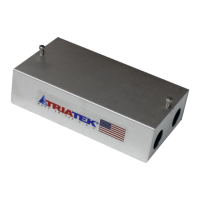
Should the UVM be supplied without the valve and any pre-
wiring, then the following items are required to wired to the unit.
The device requires that Io be connected to an actuator capable
of accepting 4 – 20 mA. The connection is from Io and any GND
connector. The device also needs a 0 -5 signal from a valve
feed back sensor. This is connected to CN3 pins G, +Vfb and
FB. G is ground or common, +Vfb is the 5 V power to power the
position sensor, and feedback is the signal from the sensor that
represents its position.
The actuator and UVM need be isolated from each other by
means of a 24/24 isolation transformer.
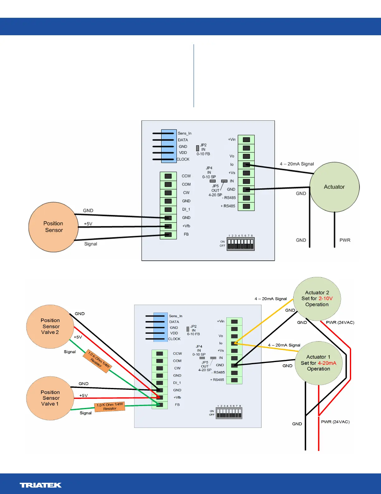
In the case of dual and other multiple combination valves of the
same size, the following wiring is used. The feedback sensors
need to have a 1K ohm ¼ W 1% resistor placed in series with
the position signal output. Only one of the actuators should have
the 4-20 mA setting, the remaining actuators should be set for
2-10 V operation.
- Vin
Figure 12. Position Sensor / Actuator Wiring
- Vin
Figure 13. Dual Valve Operation
 Loading...