UVM-1000
LIT-12013155
11
Due to continuous improvement, Triatek reserves the right to change product specications without notice.
Installation and Setup
Triatek reserves the right to change product specications without notice.
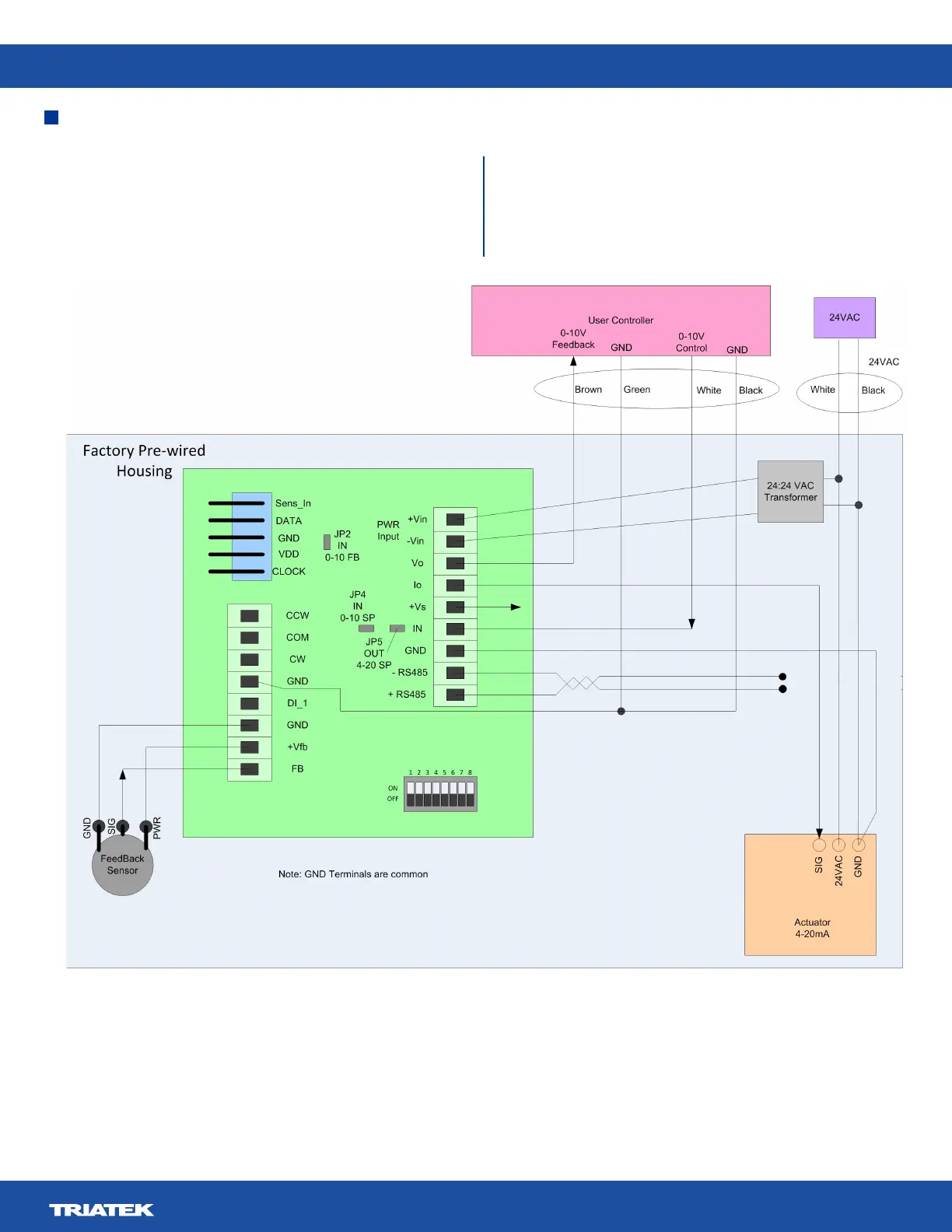
The light blue area depicts the UVM housing, and the green
area the UVM board. The actuator and feedback sensor are
already wired as is the isolation transformer. Connect 24VAC to
the supplied power tails. This feeds both the actuator and the
isolation transformer.
The 24 VAC supply needs to be capable of providing at least
25 VA, with 20 for the actuator and 5 VA for the UVM. The
0 – 10 V cfm request signal is attached to the IN connection
on the UVM board, with the ground lead going to any of the
GND connections. The feedback signal is derived from the Vo
connection and any of the GND connections.
Figure 7. Universal Valve Module Wiring
 Loading...