4-20
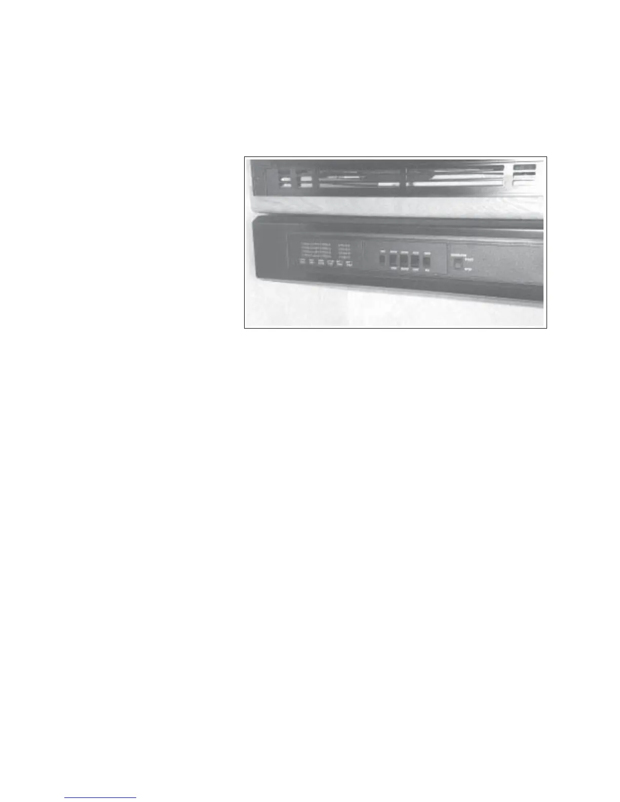
4.13 SYSTEM MONITOR
Refer to the instructions in the information package
for more details.
CLASS C MOTORHOME
Fig. 4-25 SYSTEM MONITOR
1. Generator:
This 3 position spring-loaded to
neutral center switch controls
the operation of the auxiliary
generator. Depress and hold the
upper position to start the
generator engine. Release the
switch when the engine starts.
Depress and hold the bottom
portion of the switch to stop the
engine. All motorhomes have
the generator controls pre-wired
at the factory to allow easy
subsequent installation.
2. Hood Fan:
This 2 position rocker switch controls the power
to the fan over the stove. Depress the top
portion of the switch to turn the fan on and the
bottom for off.
3. Hood Light:
This 2 position rocker switch controls the power
to the light over the stove. Depress the top
portion of the switch to turn the light on and the
bottom for off.
4. Water Heater:
This 2 position rocker switch controls the power
to the water heater. Depress the top portion of
the switch to turn the water heater on and the
bottom for off.
5. Water Pump:
This 2 position rocker switch controls the power
to the water pump. Depress the top portion of
the switch to turn the water pump on and the
bottom for off.
6. Test:
This push button switch controls the power to
the monitor test function. Depress the switch
and hold to check the adjacent system lights:
a. Battery 1 Condition:
Voltage should be 12 for full charge.
b. Battery 2 Condition:
Not used.
c. LP Gas Tank:
Measures LP gas remaining in tank.
d. Fresh Water Tank:
Display fresh water tank filled ratio.
e. Holding Tank 1 (Grey Water):
Displays grey water tank filled ratio.
f. Holding Tank 2 (Black Water):
Displays black water tank filled ratio.