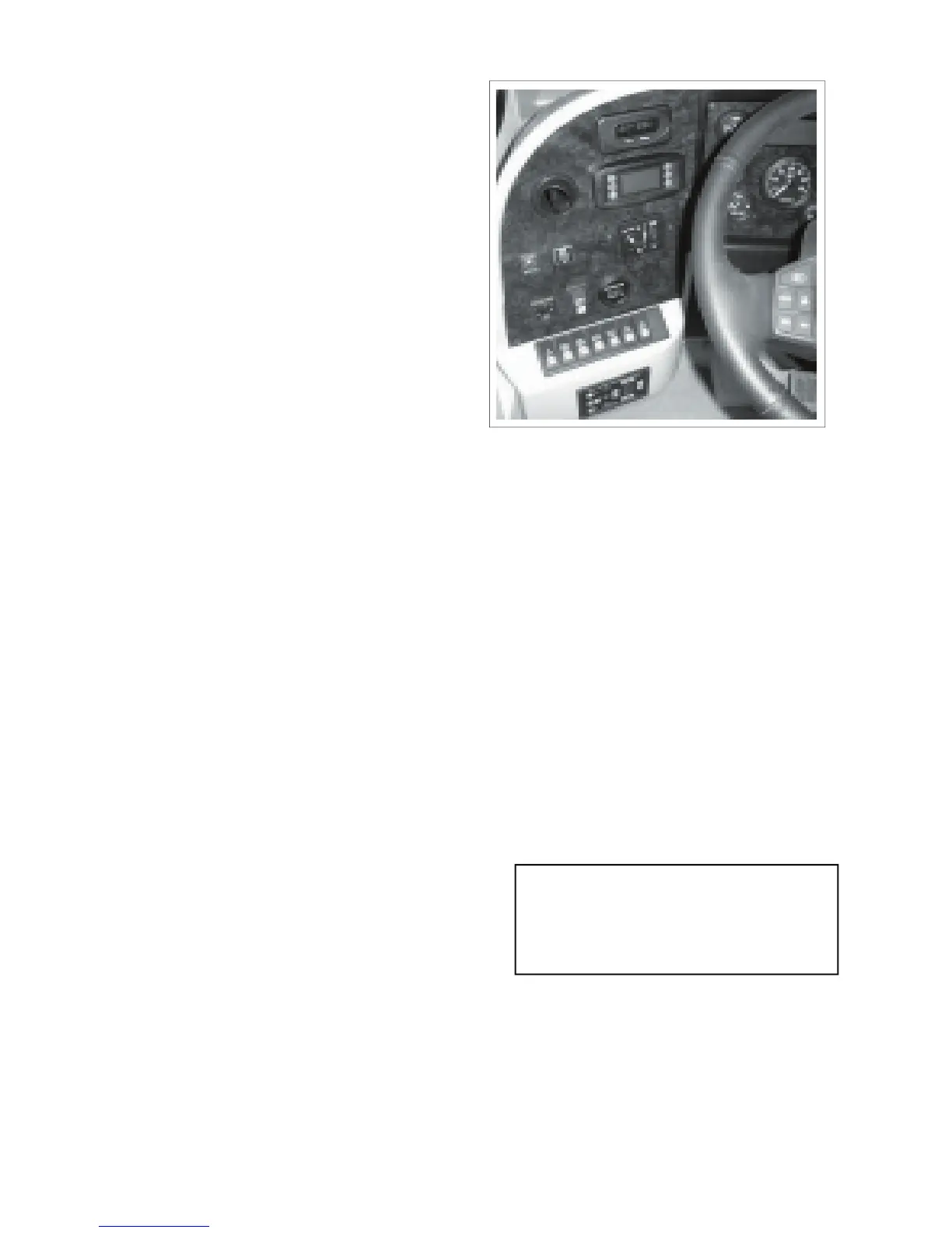
displaying text messages and graphics
to communicate reat-time information
about the status and performance of the
vehicle to the operator. This information
is organized in a menue structural format.
See RV Chassis Operator's Manual in the
Owner's Information Package for detailed
n. Jacks Down Warning Light.
This red light indicator alerts the driver that
the levelling jacks are in their 'down' position.
It comes on when the ignition switch is turned
'on' if the jacks are down.
o. TV Antenna Up Warning Light
This red light indicator alerts the driver that
the TV Antenna is in the 'up' position. The
light will go off when the antenna is lowered
in the transport position.
This standard automotive push-pull
headlight switch controls the power to the
headlight. Pull the knob out to turn the lights
on. Push the knob all the way in to turn the
r. Instrument panel brightness control:
Turn the wheel to brighten or dim the
This spring loaded push button switch
controls the air horn. Depress and hold the
switch to sound the horn. Release the switch
This push button switch controls the power
to the coach rear docking lights. Depress
the bottom portion of the switch to turn the
lights on and the top to turn them off.
This push button switch controls the power to
the side docking lights. Depress the bottom
portion of the switch to turn the side visibility
lights on and depress the top to turn off.
These lights are normally used to illuminate
the side of the vehicle when parking or
manoeuvring in cramped spaces.
This push button switch controls the power
to the exterior rear view mirror heaters.
Depress the bottom portion of the switch to
turn the heaters on and the top portion to turn
off. The heater will automatically be shut off
when the ignition switch is turned off.
This spring loaded push button switch controls
the interconnect circuit between the auxiliary
and chassis batteries. Depress and hold the
switch to connect the auxiliary batteries to
the chassis batteries. Release the switch
to disconnect. Use this interconnect only
when the chassis batteries are too run down
f. Power Sun Visor Driver Side:
This push button switch controls the power
to the electric sun visor. Depress the bottom
portion of the switch to lower the sunvisor
and depress the top portion of the switch to
g. Power Sunvisor Center (optional)
This push button switch controls the power
to the electric sun visor. Depress the bottom
portion of the switch to lower the sunvisor
and depress the top portion of the switch to
h. Blank spot: (Room to add another
k. Directional Compas with exterior
See operating insturctions in the Owner's
m. Chassis Vehicle Information Center
The Information Center is an interactive
graphical display that is capable of
EMPRESS
IMPORTANT
The Daytime Running Lights (DRL) come on
at partial power whenever the engine is run-
ning. The headlight switch must be turned
on for the headlights to operate at full power.
r
m
s
o
p
a
b
c
d
e
f
g
h
k
n
t
u
v