19
CONNECTING THE PCB CABLE
9
check list
SECTIONSECTION
CONNECTING THE PCB CABLE
& REFITTING THE COVER
IMPORTANT: After connecting the PCB cable,
please check the following before retting the
cover:
1. All plumbing connections are watertight.
2. Terminal block screws are fully tightened.
3. Make sure the pipe and cable entering
the unit do not prevent the cover locating
correctly onto the backplate.
4. Check that the top rubber seal is in place
on the inside of the cover.
• See figs.14 & 15 on page 17 for the correct
positions of the temperature spindle and
temperature knob.
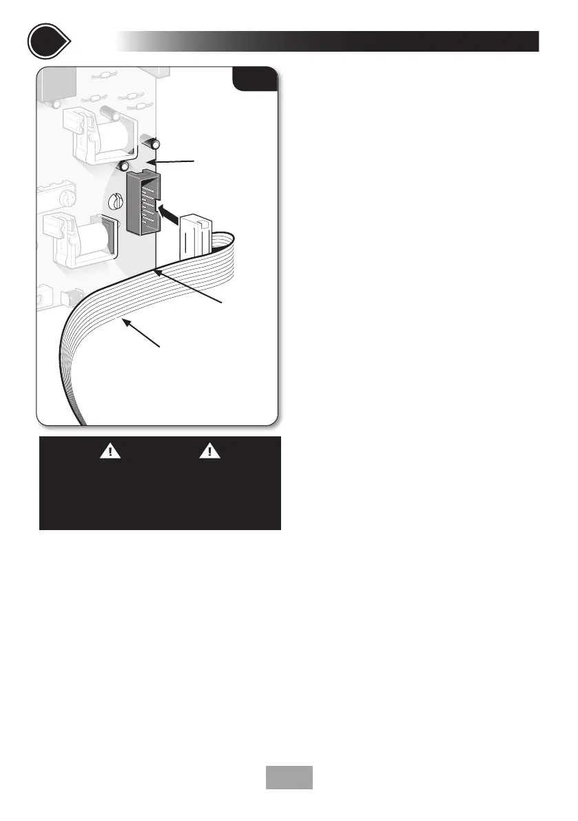
• Attached to the display PCB inside
the cover is a 10-way ribbon cable.
The ribbon cable connector must be
plugged into the socket located at the
right of the power PCB situated inside
the unit (fig.18).
• The ribbon cable has a coloured edge
which is uppermost when correctly
fitted to the socket. There is also a key
way for ensuring correct location into
the socket.
• Guide the cover into position so that the knob
spindle locates correctly (minor adjustment
may be necessary to align the knob and
spindle). Should any difficulty arise, re-check
the points above.
• While applying slight pressure to the cover,
secure in position with the retaining screws.
• Turn the electric supply back on at the
isolating switch. The ‘Power’ indicator will
light.
• Water will NOT flow until the Start/Stop
button is pressed.
• It is recommended that the water and electric
supplies to the shower are turned off while
the riser rail kit is being installed.
• The flexible hose can be left attached to the
shower outlet. Make sure the supplied sealing
washer is fitted.
Fig.18
PCB cable
(cover)
PCB (In shower)
WARNING
COVER RETAINING SCREWS
ONLY the SUPPLIED SCREWS should be
used. The use of non supplied screws WILL
invalidate product specications & warranty.
Coloured edge
 Loading...