Detector 1
Setting saved
Wate r D ete cto r
110 V
A1
Wate r D ete cto r
24 V
A1
110 V
A6
A6
24 V
Aqua-X Controller
Water Detector
NOTES:
1.
Each Water Detector can be assigned to a Control Board
which
has been successfully assigned to the Aqua-X Controller. The
Water Detector can not be assigned to an unassigned Control
Board.
2. One Water Detector can be
assigned
to only one 24V or 110V
output. One Aqua-X Controller can connect up to 30pcs Water
Detectors.
3.
If the
assigned
output of that board is offline, the output symbol
will
blink on the LCD display of the Aqua-X Controller.
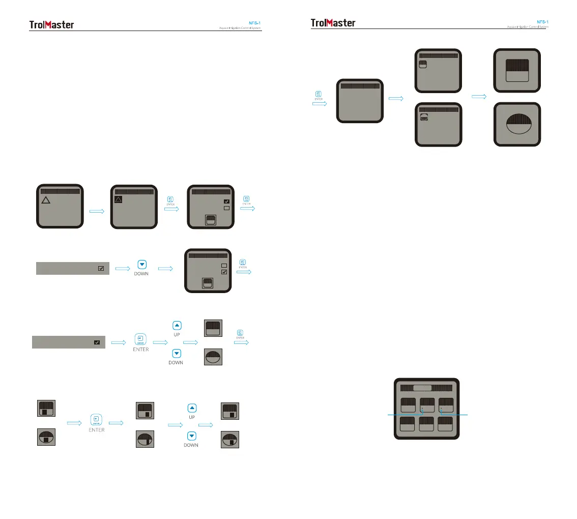
4. If the output is successfully
assigned
with the Water Detector
and the Water Detector is connected with the Aqua-X Controller,
there is a dot before the
assigned
output on the Control Board
interface as below illustration.
Board
110 V
C
110 V
C1
110 V
C2
110 V
C3
110 V
C4
110 V
C5
110 V
C6
Control Board Interface
Dot
(Indicating Assigned
Output)
Dot
(Indicating Assigned
Output)
Wate r D ete cto r
1
Wate r D ete cto r
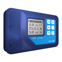
b. Assignment (Output Assigned Mode)
The default mode of Water Detector is in Leak Sensor (Leak Detection
Mode). You can change the Leak Detection Mode (Leak Sensor) into
Output assigned Mode (Assignment) as below processes. As one Water
Detector can be assigned to only one output on any Control Board,
you need to select 24V or 110V and one of six outputs to be assigned
with the Water Detector. When the output has been successfully
assigned, the Water Detector will send alarm message to your Smartphone
one minute later when it detects no water on the reservoirs of the
irrigation system.
1
Detector 1
Leak Sensor
Assignment
110 V
A1
Detector 1
Leak Sensor
Assignment
110 V
A1
Leak Sensor
Blinking
Assignment
Blinking
or
or
or
A1
24 V
110 V
or
24 V
A1
A1
110 V
or
24 V
A1
A1
110 V
or
24 V
A6
A6
110 V
A1
22 23
 Loading...